


500-19-54 Dual Channel Telephone Interface
Issue 1.2 Trilogy Communications Limited Page 13 of 19
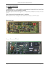
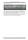
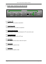
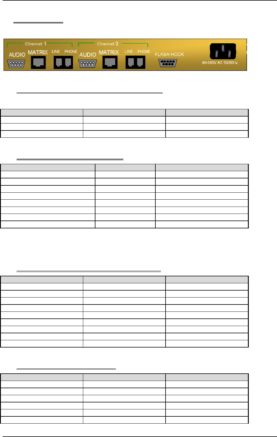
4. CONNECTORS
Rear view
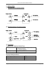
4.1 Mains connector - Power connection. IEC mains
Pin Number Signal Direction From Unit
L Live Input
N Neutral Input
E Earth Input
4.2 Matrix connector – RJ45 connector
Hybrid RJ45 (“Matrix”) Hybrid Signal Matrix RJ 45
1 – pair 1 Data RX (a) 1 – pair 1
2 – pair 1 Data RX (b) 2 – pair 1
3 – pair 2 Data TX (a) 3 – pair 2
4 – pair 3 Audio in (b) 4 – pair 3
5 – pair 3 Audio in (a) 5 – pair 3
6 – pair 2 Data TX (b) 6 – pair 2
7 – pair 4 Audio out (a) 7 – pair 4
8 – pair 4 Audio out (b) 8 – pair 4
Note: Please ensure that any cables are correctly wired, following the 4-pair wiring indicated
above. Failure to do so may lead to incorrect operation of the hybrid frame.
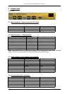
4.3 Audio connector. 9w D chassis plug connector.
Pin Number Signal Direction From Unit
1. Chassis ground Switch Ground
2. Seize Switch Input
3. Drop Switch Input
4. Audio Out (-) Output
5. Audio in (-) Input
6.
7.
8. Audio out (+) Output
9. Audio in (+) Input
4.4 Line connector. RJ11 connector.
Pin Number Signal Direction From Unit
1.
2.
3. Line + Input / Output
4. Line - Input / Output
5.
6.