20 Agilent N5161A/62A/81A/82A/83A MXG Signal Generators Installation Guide
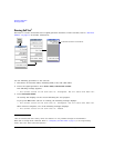
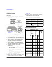
Operation Verification
Frequency Range and Accuracy Check
Spectrum Analyzer Procedure
(N5161A
1
/62A
1
/81A/82A/83A)
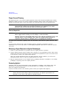
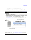
Test Setup
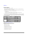
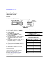
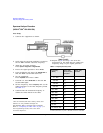
1. Connect the equipment as shown.
2. Verify that the spectrum analyzer is locked to
the 10 MHz external reference frequency.
3. Align the spectrum analyzer:
Press
System > Alignment > Align All Now.
4. Preset the signal generator: Press
Preset.
5. Turn modulation off: Press the
Mod On/Off so
that the MOD On/Off LED turns off.
6. Set the amplitude:
Press
Amplitude and enter 0 dBm.
7. Turn RF on: Press
RF On/Off so that the RF
On/Off LED lights.
8. Set the frequency: Press
Frequency and set the
signal generator to the first frequency listed
in Table 3-3.
9. Confirm that the measured frequency is
within the limits listed in the table.
1.For the N5161A/62A these softkey menus and
features are only available through the
Web-Enabled MXG or through SCPI commands.
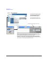
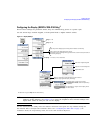
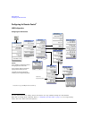
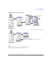
Refer to “Configuring the MXG ATE” on page 7, to
the Programming Guide, and to the SCPI
Command Reference.
10. Repeat step 8 and step 9 for all of the
frequencies in the table that are within the
frequency range of your signal generator.
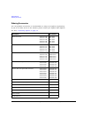
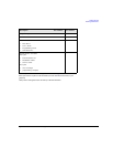
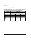
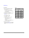
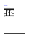
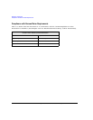
Table 3-3 Frequency Accuracy Limits
Frequency
(MHz)
Limit (Hz)
N5161A/62A/
81A/82A
Limit (Hz)
N5183A
0.1 MHz
a
a.N5181A/82A with s/n prefix: < MY4740, measure at 0.25 MHz
±2 ±2
200 MHz ±2 ±2
300 MHz ±2 ±2
500 MHz ±2 ±2
1000 MHz ±2 ±2
2000 MHz ±2 ±2
3100 MHz ±2 ±2
6000 MHz ±2 ±4
10 GHz -- ±4
20 GHz -- ±8
32 GHz/40 GHz -- ±16