22 Agilent N5161A/62A/81A/82A/83A MXG Signal Generators Installation Guide
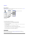
Operation Verification
Checking the Output Power
N5161A
1
/81A Test Procedure
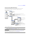
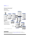
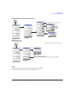
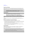
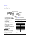
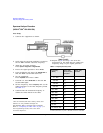
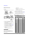
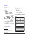
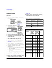
Test Setup
1. Zero and calibrate the power sensor to the
power meter:
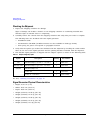
2. Connect the equipment as shown:
3. Preset the signal generator: Press
Preset.
4. Turn RF on: Press
RF On/Off so that the RF
On/Off LED lights.
5. Turn modulation off: Press
Mod On/Off so that
the Mod On/Off LED turns off.
6. Set the frequency: Press
Frequency and enter
the first frequency value listed in Table 3-8.
7. Set the amplitude: Press
Amplitude and enter
the amplitude value for that frequency.
8. Configure the power meter for the
measurement.
a. Press the
Frequency Cal Fac button on the
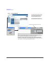
1.For the N5161A/62A these softkey menus and
features are only available through the
Web-Enabled MXG or through SCPI commands.
Refer to the Programming Guide or to the SCPI
Command Reference.
power meter.
b. Select a power meter channel (if
applicable).
c. Use the arrow keys to enter the frequency
at which to measure the power.
9. Measure the output power level.
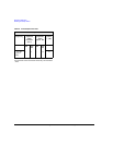
10. Repeat steps 6 through 9 to measure power at
each of the 15 frequencies listed in Table 3-8.
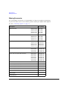
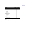
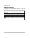
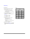
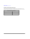
11. Confirm that the measured power levels are
within the limits listed in the table.
NOTE Limit values are due to power meter
uncertainty.
Table 3-4 Leveled Output Power Limits
N5161A/81A Output Power
Frequency Amplitude (dBm) Limits
(dB)
125 MHz 7 ±2
275 MHz 7 ±2
338 MHz 7 ±2
425 MHz 7 ±2
538 MHz 7 ±2
675 MHz 7 ±2
850 MHz 7 ±2
1075 MHz 7 ±2
1350 MHz 7 ±2
1700 MHz 7 ±2
2150 MHz 7 ±2
2700 MHz 7 ±2
3400 MHz 7 ±2
4300 MHz 7 ±2
5400 MHz 7 ±2