25 Agilent N5161A/62A/81A/82A/83A MXG Signal Generators Installation Guide
Operation Verification
Checking the Output Power
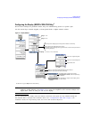
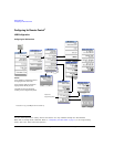
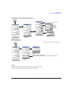
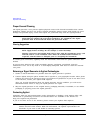
N5183A Test Procedure
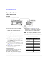
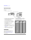
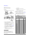
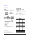
Test Setup
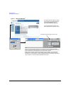
1. Zero and calibrate the power sensor to the
power meter:
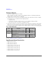
2. Connect the equipment as shown:
3. Preset the signal generator: Press
Preset.
4. Turn RF on: Press
RF On/Off so that the RF
On/Off LED lights.
5. Turn modulation off: Press
Mod On/Off so
that the Mod On/Off LED turns off.
6. Set the frequency: Press
Frequency and
enter the first frequency value listed in
Table 3-8.
7. Set the amplitude: Press
Amplitude and
enter the amplitude value for that frequency.
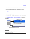
8. Configure the power meter for the
measurement.
a. Press the
Frequency Cal Fac button on
the power meter.
b. Select a power meter channel (if
applicable).
c. Use the arrow keys to enter the frequency
at which to measure the power.
9. Measure the output power level.
10. Repeat steps 6 through 9 to measure power
at each of the 15 frequencies listed in
*Refer to Table 3-7
on page 25
*Refer to Table 3-7
on page 25.
Table 3-8.
11. Confirm that the measured power levels are
within the limits listed in the table.
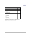
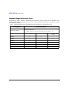
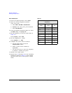
Table 3-7 Power Sensors by Frequency and Options
N5183A Frequency Power Sensor
Option
520/540
< 5GHz E9304A
Option 520 >
5GHz 8485A
Option 540 >
5GHz 8487A
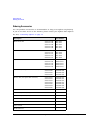
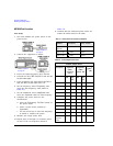
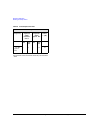
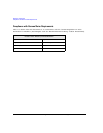
Table 3-8 Leveled Output Power Limits
N5183A Output Power
Frequency Amplitude
(dBm)
Standard
Power
Amplitude
(dBm)
Option 1EA
Limits
a
b
(dB)
520 532/
540
520 532/
540
200 MHz 11 7 15 14 ±2
300 MHz 11 7 15 14 ±2
500 MHz 11 7 15 14 ±2
800 MHz 11 7 15 14 ±2
1.0 GHz 11 7 15 14 ±2
2.0 GHz 11 7 15 14 ±2
3.1 GHz 11 7 15 14 ±2
5.0 GHz 11 7 18 15 ±2
10 GHz 11 7 18 15 ±2
20 GHz 11 7 18 13 ±2
31.8 GHz
(Option
532)
-- 7 -- 13 ±2