English – 37
2
1
1
2
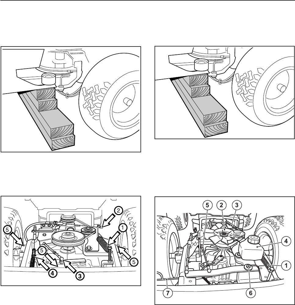
Removing/installation of hydrostatic
transmission Rider 13 H/13 H Bio and
Rider 16 H
Removal/installation of gear box
Rider 11
• Block-up the machine in front of the rear frame
and dismantle the rear wheels.
• Remove the cover from over the gear box.
• Lower the garage jack and pull out the gear box.
• Installation of the gear box is carried out in the
reverse removing gear box order
• After installation, check that the clutch, brake
and gear wires are correctly adjusted (see
“Checking and adjusting brake wire”, “Checking
and adjusting gear control” and “Checking and
adjusting freewheel clutch”).
• Release the tensioning wheel spring (1).
• Unfasten the clutch wire (2), and detach the belt
from the gear box pulley.
• Detach the gear and brake wires (3 and 4).
• Insert a garage jack under the gear box and
unscrew the gear box's five holder screws (5).
3
Reparation instructions
• Block-up the machine in front of the rear frame
and remove the back wheels.
• Remove the transmission cover.
• Release the tensioning wheel spring (1).
• Remove the fan (2), it is held by a circlip.
• Work off the drive belt (3).
• Remove the oil tank (4).
• Release the brake wire spring and remove the
brake wire from the brake lever (concealed under
the oil tank).
• Release the hydrostatic transmission link (5) in
the front ball joint.
• Remove the screw (6) holding the arm.
• Remove the freewheel clutch control (7) with its
spring.


