17
Speeds 1, 2, or 3: Best used for fine centering of an object in the field of view of a
higher power eyepiece, such as a 12mm or a 9mm eyepiece.
Speeds 4, 5, or 6: Enables centering an object in the field of a low-to-moderate power
eyepiece, such as the standard Super Plössl 26mm.
Speeds 7 or 8: Best used for rough centering of an object in the viewfinder.
Speed 9: Moves the telescope quickly from one point in the sky to another.
Observe the Moon
Point your telescope at the Moon (note that the Moon is not visible every night). Use
your EC handbox or Autostar to practice using the Arrow keys and the slew speeds to
view different features. The Moon contains many interesting features, including
craters, mountain ranges, and fault lines. The best time to view the Moon is during its
crescent or half phase. Sunlight strikes the Moon at an angle during these periods and
adds a depth to the view. No shadows are seen during a full Moon, making the over-
ly bright surface to appear flat and rather uninteresting. Consider the use of a neutral
density Moon filter when observing the Moon. See
OPTIONAL ACCESSORIES, page
38. Not only does it cut down the Moon's bright glare, but it also enhances contrast,
providing a more dramatic image.
Tracking Objects
As the Earth rotates beneath the night sky, the stars appear to move from East to
West. The speed at which the stars move is called the sidereal rate. You can setup
your telescope to move at the sidereal rate so that it automatically tracks the stars and
other objects in the night sky. The tracking function automatically keeps an object
more or less centered in the telescope’s eyepiece.
To automatically track objects, you first need to learn how to set the polar home position
of your telescope and then how to select "Targets: Astronomical" from the Autostar
Setup menu. EC handbox users, see
APPENDIX D, page 58, for more information.
Setting the Polar Home Position
1. Level the mount, if necessary, by adjusting the length of the three tripod legs.
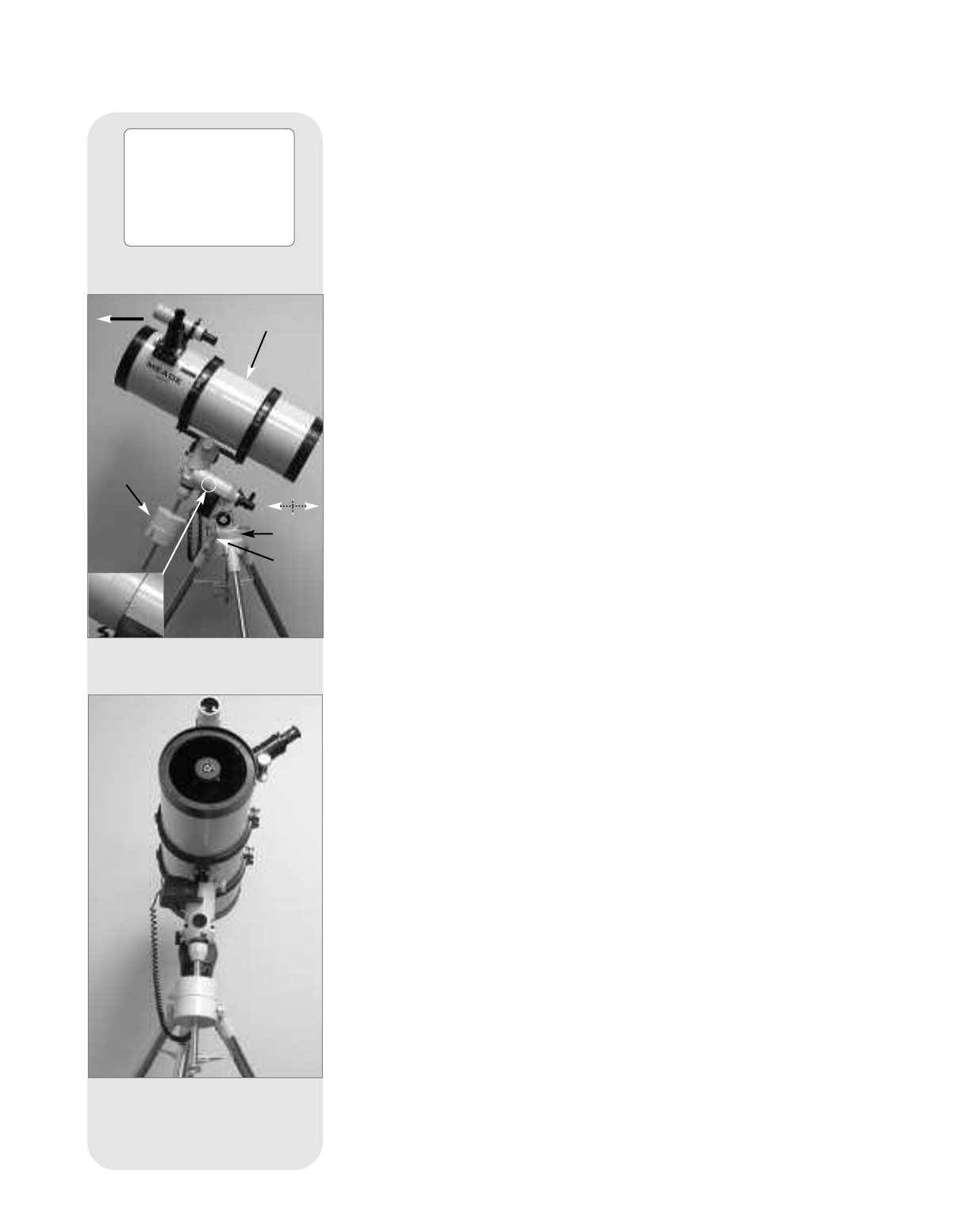
2. Unlock the R.A. Lock (33, Fig. 1d). Rotate the Optical Tube Assembly until the
counterweight shaft is pointing straight down over the mount. See Figs. 16a and
16b.
3. If you have not already done so, lift the telescope assembly and turn it so the
tripod leg below the Fine Azimuth Control Knobs (27, Fig. 1c) approximately
faces North (or South in the Southern Hemisphere). Release the Dec. lock (17,
Fig. 1d) of the tripod, so that the optical tube (10, Fig. 1a) may be rotated. Rotate
the optical tube until it points North (or South in the Southern Hemisphere). Then
re-tighten the lock. Locate Polaris, the North Star, if necessary, to use as an
accurate reference for due North (or Sigma Octantis in the Southern
Hemisphere). See
LOCATING THE CELESTIAL POLE, page 51.
4. If you have not already done so, determine the latitude of your observing location.
See
APPENDIX C: LATITUDE CHART, page 57, for a list of latitudes of major cities
around the world. Use the latitude T-handle screws (26, Fig. 1d) to tilt the tele-
scope mount so that the pointer indicates the correct latitude of your viewing loca-
tion on the latitude dial (
28, Fig. 1d). See step 6, page 12 for more information.
5. If steps 1 through 4 above were performed with reasonable accuracy, your tele-
scope is now sufficiently well-aligned to Polaris, the North Star, for you to begin
making observations.
Once the mount has been placed in the polar home position as described above, the
latitude angle need not be adjusted again, unless you move to a different geographi-
cal location (
i.e., a different latitude).
Important Note: For almost all astronomical observing requirements,
approximate settings of the telescope’s latitude and other settings are
acceptable. Do not allow undue attention to precise settings of polar home
position of the telescope to interfere with your basic enjoyment of the
instrument.
Note: If you wish to per-
form a more precise
polar alignment for the
purposes of astrophotog-
raphy, see "Appendix B,"
page 52.
Fig. 16a: The polar home position,
side view. Inset: Line up triangles on
the mount.
Fig. 16a: The polar home position,
front view.
Level
Mount
Fine
Azimuth
Control
Knobs
Point optical
tube to North
Point
counterweight
shaft straight
down over
mount.
North
