MODENA 80 E
21
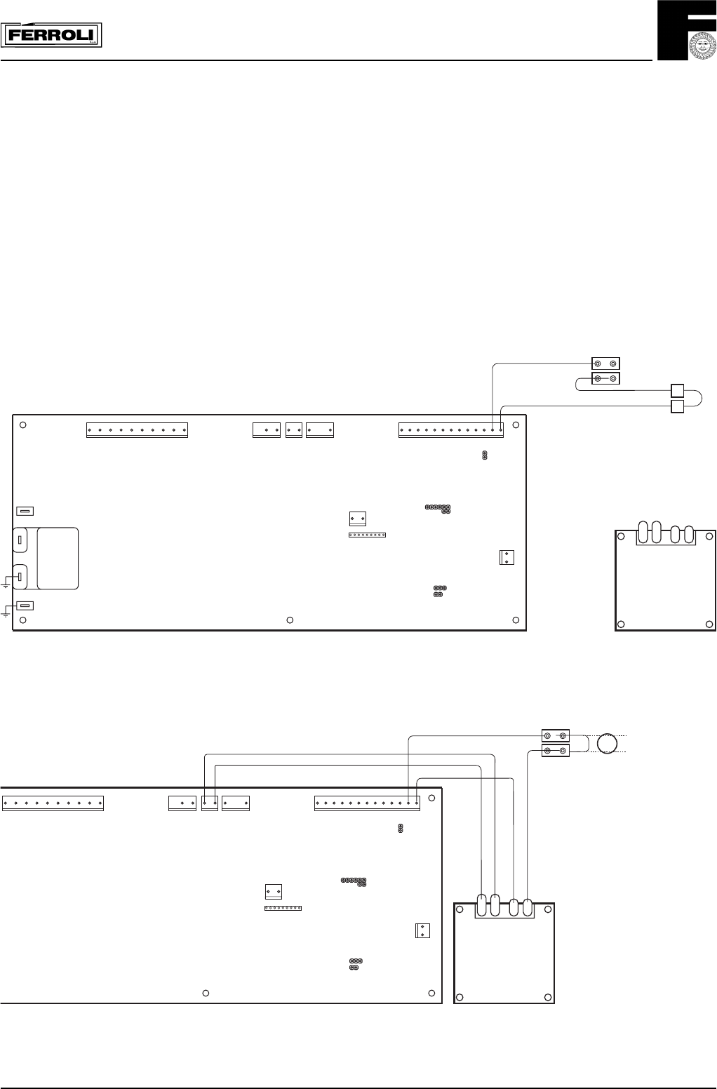
Fig. 30
Terminal 4 & 5 situated
underneath the boiler in the
terminals compartment
Terminals for integral clock
situated inside circuit board
compartment
Existing wiring
- Remove outer case by removing two securing screws from the rear bottom corners and lift off.
- Remove screw securing facia panel and swing facia panel down.
- Remove rear cover from facia.
- Remove clock blanking plate from the boiler facia panel.
- Mount clock into facia panel using two screws and spacers provided.
- Take the black cable containing the blue and brown wires and connect the loose spades to clock terminals 1 & 2.
- Connect the plug end of the cable to terminal X2 of main circuit board.
- Remove the connector link from the 2 wires located behind the clock position.
- Connect these to terminal 3 and 5 of the clock.
- Replace everything in reverse order.
- Please refer to page 55 of User manual for use of time clock
X6
X1
X2 X3
X4
12121312345678910 12345678910111213
21
X5
X12
12
123456789
X10
X8
X7
MF03F
JP02
JP01
JP03
Nat/LPG
X11
CLOCK
Fig. 31
X1
X2 X3
X4
12121312345678910 12345678910111213
21
X5
X12
12
123456789
X10
MF03F
JP02
JP01
JP03
Nat/LPG
X11
CLOCK
4
3
72
VOLTAGE
FREE
SWITCH
Wiring for integral clock and/or external controls
External control
i.e. Room Stat/Clock


