MODENA 80 E
30
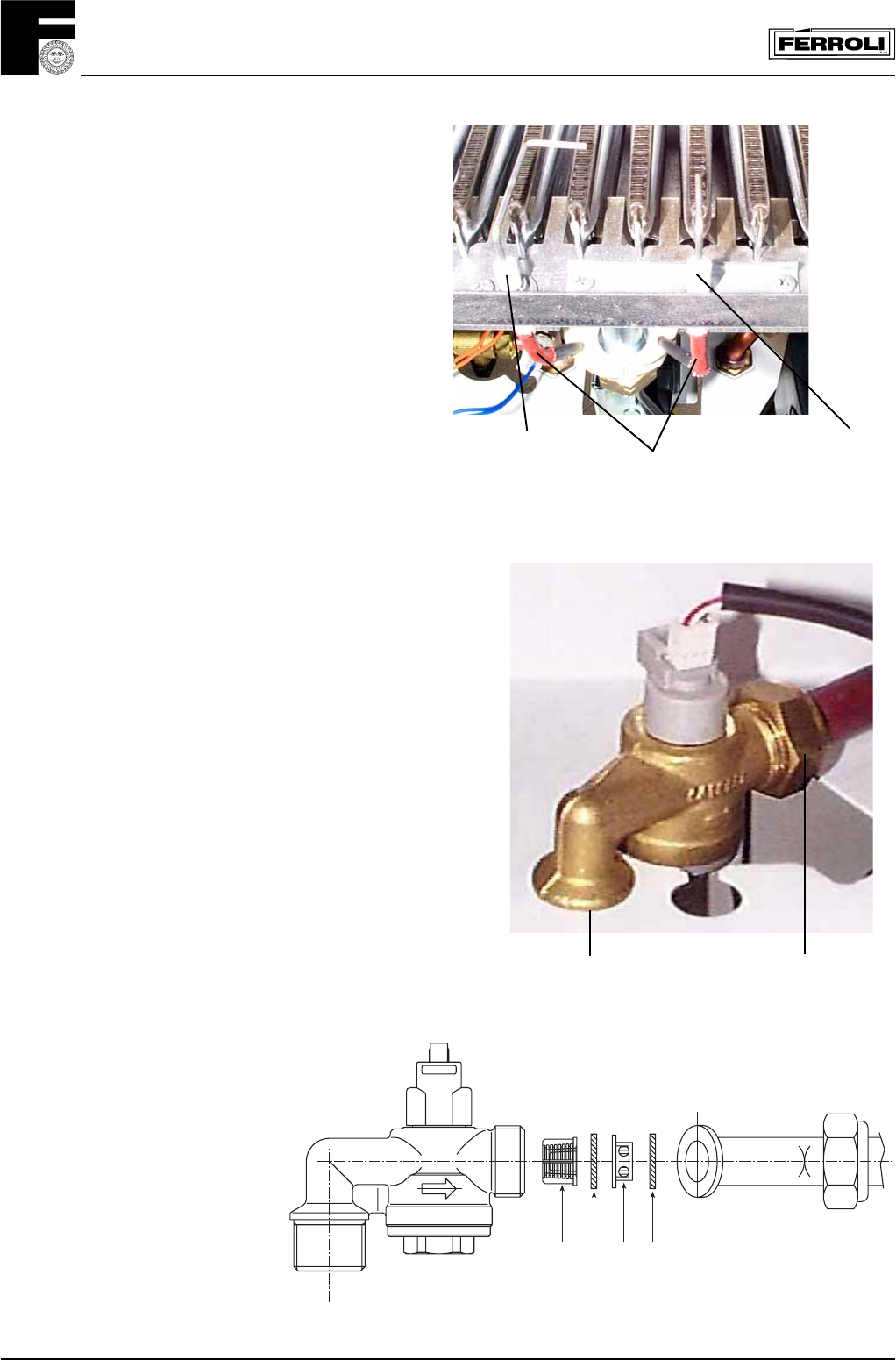
7.12 Spark or flame detect electrode
(fig. 43)
• Isolate gas and electricity supply
• Remove outer case (two screws bottom rear
corners)
• Open room sealed compartment and
combustion chamber
• Identify electrode from fig. 43
• Unplug electrical connection "A" from sensing
electrode
• Remove fixing screw and remove flame detect
electrode
• Remove the two fixing screw from spark
electrode plate and remove it.
Spark
A
Flame
detect
Fig. 43
7.13 D.H.W. flowmeter
• Isolate electricity and water supplies
• Open a hot water tap to release water
pressure from the domestic side of the heat
exchanger, close tap.
• Remove outer case (two screws bottom rear
corners).
• Remove two screws from control panel and tilt
forward
• Take off protective cover from main PCB and
unplug flow meter lead from terminal X6
• Place a piece of cloth or some other
absorbent material over rear of control panel to
catch any drops of water that may be released
when removing the flow meter
• Using a 24mm open ended spanner, undo flow
meter unions "A" and "B" taking care not to twist
the copper tubing (access through base panel).
• Remove flow meter, check + clean filter + restrictor
+ fit to new flow meter.
• Reassemble in reverse order.
Fig. 44a
A
B
37 3938 38
Key
37 Cold water inlet filter
38 Gasket
39 Cold water flow limiter
Take care on correct position of
components as reported in fig. 44b
Fig. 44b


