Rockwell Automation Publication 1412-UM001D-EN-P - September 2012 19
Operation Chapter 2
Current Sensors
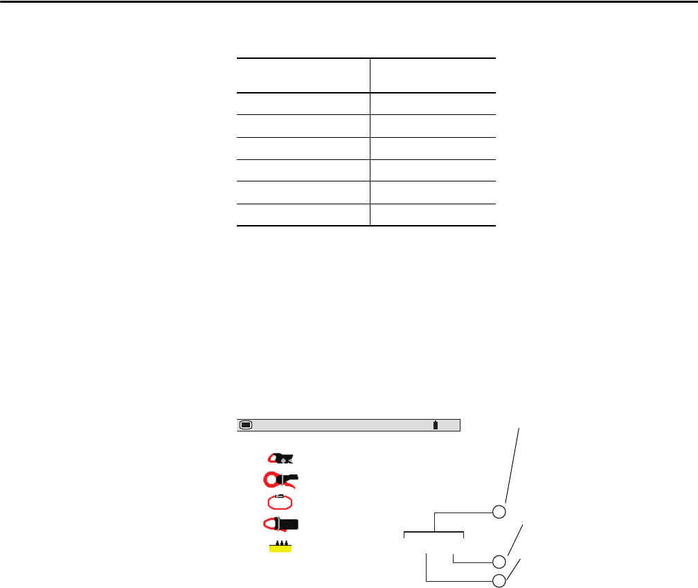
Follow these steps the select the current sensor type.
1. Highlight CURRENT SENSORS with the Up/Down Cursor buttons,
then press Enter.
This screen appears.
2. Choose the sensor type with the Up/Down Cursor buttons.
The MN Clamp also requires a range selection to match your probe. The
range choices are 200, 100, and 5 A. The 200 A range is used for the
MN93 Probe and the 100 or 5 A range is used for the MN193 Probe.
a. To select the proper range, first ensure that the MN Probe choice is
highlighted by using the Up/Down Cursor buttons.
b. Press the Left Cursor button to highlight the range, then press either of
the Up/Down Cursor buttons to select the desired measurement range
of 200, 100, or 5 A.
If the 5 A range is selected, a choice for programming the ratio is
offered.
c. To change the ratio, press the Left Cursor button to highlight the
secondary value.
d. Press either of the Up/Down Cursor buttons to toggle this value to
either 1 or 5.
e. After making this selection, press the Left Cursor button to adjust the
primary value.
Table 1 - Synchronization of the Display in Waveform Mode
Display Selection
(Vertical Right Menu)
Reference Channel
for Synchronization
3U U1
3V V1
4A / 3A A1
L1 V1
L2 V2
L3 V3
MN clamp
SR clamp
AmpFlex
MR clamp
Adapter
200A
1000 /5A
07/25/02 10:26 100
%
1
2
3
Current transducer ratio.
Left/Right Cursor buttons moves the cursor to
select the digit to edit.
Up/Down Cursor buttons increases or
decreases the value at the highlighted
position.
Secondary current value.
Nominal value of primary current from
5…2999 A.


