Rockwell Automation Publication 1412-UM001D-EN-P - September 2012 31
Display Modes Chapter 3
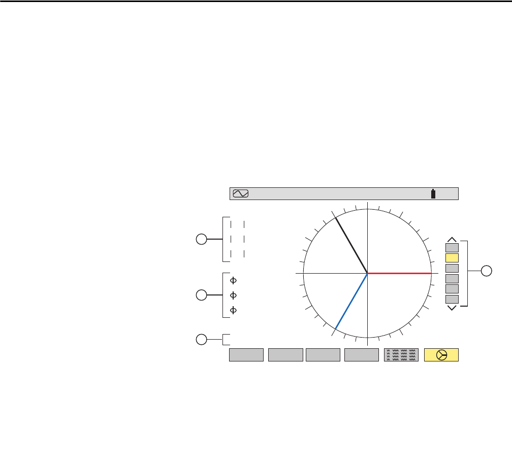
Phasor Diagram Display (Fresnal Diagram)
Absolute value of voltage or current, depending on display selection.
12 corresponds to phase angle between channel 1 and 2.
23 corresponds to phase angle between channel 2 and 3.
31 corresponds to phase angle between channel 3 and 1.
Current or voltage unbalanced ratio.
Phasor diagram displays selection by voltage, current or phase.
K factor is only available for currents 4 A, 3 A, or 2 A, depending on hook up.
Flicker is only available for voltages 3V or 2V, depending on hook up.
Flicker and K factor are available when either L1, L2, or L3 is selected from the
choices on the right side of the screen.
The DC current will be displayed, however the values are only valid when a
current probe capable of measuring DC is used. The MR193 probe is available
for this purpose.
This is valid for currents (4 A and 3 A) and for single voltage (3V). When
the user chooses to look at a specific phase (L1, L2 or L3) fVA is the
phase angle of V in relation to A.
V1
V2
V3
12
23
31
UNBALANCE
V3
V1
V2
RMS
202.8 v
1.5
%
198.7 v
203.2 v
+122 °
+118 °
+120 °
3U
3V
4A
L1
L2
L3
THDCF
max
min
07/25/0259.99Hz 10:26 100
%
4
1
2
3


