Publication 1771-6.5.132 - June 2000
2-4 Planning Your Configuration and Data Mapping Your Devices
RediSTATION Operator Interface Data Mapping
The RediSTATION has both inputs and outputs that must be mapped.
The input byte is mapped to the 1771-SDN module’s block transfer
read data table and then to the PLC-5 processor’s input data file. The
output byte is mapped to the 1771-SDN module’s block transfer write
data table and then to the PLC-5 processor’s output data file.
The mapping procedure, using RSNetWorx for DeviceNet software, is
described on pages 4-14 to 4-17.
In the RediSTATION’s bits for the red and green buttons and the
indicator light status bit:
•
1 = ON
• 0 = OFF
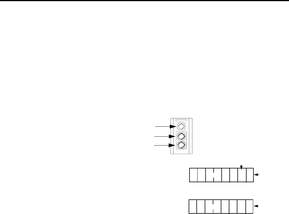
RediSTATION operator interface
Two input bits from the RediSTATION will
be mapped: bit 1 for the green Start button
and bit 0 for the red Stop button.
Bit 4 of the input byte indicates if the bulb
is missing.
Indicator light
green start light
red start light
1 byte
input
output
1 byte
The RediSTATION
operator interface
produces one byte of
input data and uses one
byte of output data.
L
start bit (green button)
stop bit
(red button)
status bit for
indicator light
One output bit for the RediSTATION’s
indicator light (on/off) will be mapped.
7
6543210
7
6
543
2
10
G R


