13
PRELIMINARY
1 Basic Operation (continued)
1.3 Operating Principles
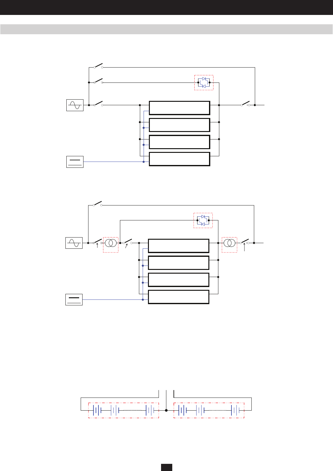
1.3.1 System Layout
Q1 LOAD
MAIN
Q2
20kVA/3U POWER MODULE
20kVA/3U POWER MODULE
20kVA/3U POWER MODULE
20kVA/3U POWER MODULE
BATTERY
Manual Input
Bypass Input
Main
STS
Q4
Output
Circuit Breaker
Q3
Manual Bypass
Circuit Breaker
Bypass Input
Circuit Breaker
Main Input
Circuit Breaker
Fig 1.3.1a System Block Diagram for KX models
Fig 1.3.1b System Block Diagram for K and KTV models
Fig 1.3.2a Battery Strings
Q1
Q3
Q4
LOAD
MAIN
Q2
XFMR XFMR
20kVA/3U POWER MODULE
20kVA/3U POWER MODULE
20kVA/3U POWER MODULE
20kVA/3U POWER MODULE
BATTERY
Manual Input
Manual Bypass
Circuit Breaker
Bypass Input
Circuit Breaker
Main Input
Circuit Breaker
Output
Circuit Breaker
Bypass Input
STS
The SU-Series 3-Phase UPS is confi gured with 3-phase 20kVA power modules that can be paralleled for redundancy or capacity upgrades. Each
KX- (Figure 1.3.1a), K- , and KTV-series (Figure 1.3.1b) UPS includes three key functions:
1) A central bypass static switch, which causes a critical load to automatically bypass any overload or fault conditions that occur.
2) A maintenance bypass switch, which eliminates UPS faults by supplying a critical load.
3) A matched transformer, which increases and decreases the input/output voltage
1.3.2 Internal Battery Layout
An internal battery pack (number of packs vary by model) supplies the UPS system with battery backup power. Each internal battery pack consists
of 40 12Vdc VRLA batteries arranged in two strings: one string of 20 positive batteries (black cable) and one string of 20 negative batteries (red
cable). The two strings are connected by a neutral (N) point (Figure 1.3.2a).
12Vdc, 20pcs 12Vdc, 20pcs
B+ N B-


