66
PRELIMINARY
2 Theory of Operation (continued)
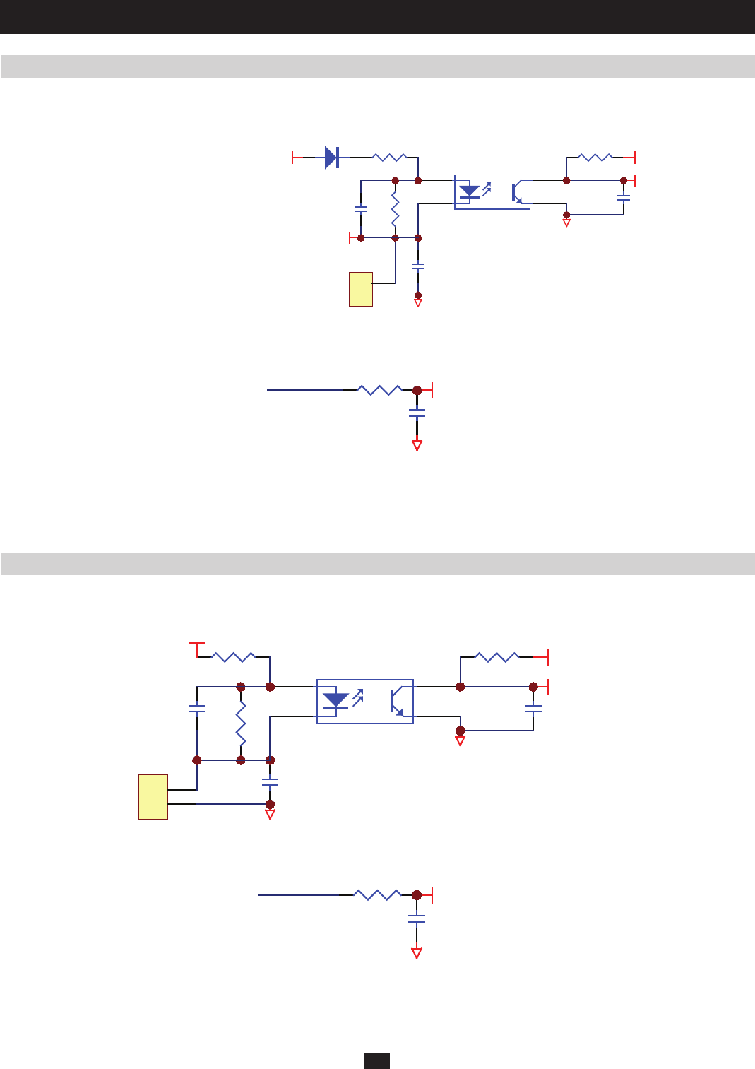
2.19 Detection Circuit for Manual Bypass Switch
2.20 Detection Circuit for Output Breaker
Located on NH-SYS-R board (Circuit for RS232, Output Dry Contact, Parallel Port, Connector to connect with each Power Module,
Circuit for 2 Slots)
Located on NH-SYS-R board (Circuit for RS232, Output Dry Contact, Parallel Port, Connector to connect with each Power Module, Circuit for 2
Slots)
Located on NH-SYS-M board (System MCU and Control Circuit)
Located on NH-SYS-M board (System MCU and Control Circuit)
RR1 02
+12VSF
RR1 07
CR6 6
RR1 03
5VS
CR6 5
1
2
4
3
UR43
G1
TOMBYP
#TOMBYP_I
CR7 3
1
2
CNR13
G4
TO Manual Bypass Breaker
DR15
(6)
RM1 46
CM102
G1
#TOMBYP_I
TOMBYP_I
(a) CNR13 connects to the auxiliary contact of the manual bypass switch.
(b) System MCU detects the status of the manual bypass switch via TOMBYP_I (6). Manual bypass switch will stay in the OFF position and
TOMBYO_I (6) will be high.
(a) CNR10 connects to the auxiliary contact of the output breaker.
(b) System MCU detects the status of the output breaker via OPCBAUX_I (72). Output breaker stays in the OFF position and OPCBAUX_I (72)
will be high.
RR7 5
+12VSF
RR7 9CR5 4
RR7 4
5VS
CR5 3
1
2
4
3
UR33
G1
#OPCBAUX_I
CR5 8
1
2
CNR10
G4
(72)
RM15 1
CM108
G1
#OPCBAUX_I
OPCBAUX_I


