


485DSS3298 Manual 3
B&B Electronics -- PO Box 1040 -- Ottawa, IL 61350
PH (815) 433-5100 -- FAX (815) 434-7094
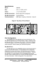
RS-232 Port
The RS-232 DTE port is an asynchronous port that supports TD
and RD signals. In order to make the proper connections to the RS-
232 port. It is necessary to have a basic understanding of the terms
DCE and DTE. The original design for connecting RS-232 devices
together uses DB25 connectors, and connects a DTE (Data
Terminal Equipment) device to a DCE (Data Communication
Equipment) device. Each device will have inputs on pins that
correspond to outputs on the same pins of the other device. For
example, a DTE device transmits data out on pin 2 and a DCE
device receives data in on pin 2. IBM PC's are DTE devices and
modems are DCE devices. Only TD and RD of the RS-232 port
pass through to the RS-485 port when the 485DSS is ON. The
485DSS raises and lowers the RTS output signal on the RS-232 port
to reflect the connect state of the port. This signal can notify the RS-
232 device to start communicating to the Host or it can be an alarm
output. The Host can monitor the CTS input line to determine if the
RS-232 device is requesting access to the network. This input line
could also be an alarm input. NOTE: If using RTS or CTS lines as
alarms the user may have to design additional circuitry to properly
interface to the alarm circuits. Refer to cable charts in Appendix C
for making your own cables.
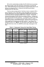
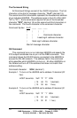
Table 1. RS-422/485 Port
Terminal
Block
Signal Description
RS-422/485
Signal
Direction of
Port
FR GND Frame Ground <------>
TD(A)(-) Transmit Data (A)(-) Output
TD(B)(+) Transmit Data (B)(+) Output
RD(A)(-) Receive Data (A)(-) Input
RD(B)(+) Receive Data (B)(+) Input
GND Signal Ground <------>
+12VDC Power Supply Input