


4 485DSS3298 Manual
B&B Electronics -- PO Box 1040 -- Ottawa, IL 61350
PH (815) 433-5100 -- FAX (815) 434-7094
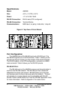
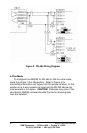
RS-422/485 Wiring
RS-485 receivers also have an enable/disable control line. The
2W/4W jumper selects when to enable and disable RS-485 receiver.
Setting the jumper to the 4W position constantly enables the
receiver which is the same as operating in an RS-422/485 4-wire
mode. In this position and connected to a 2-wire network, all data
being transmitted by the RS-485 driver echos back through the RS-
485 receiver. Setting the jumper to 2W (RS-485, 2-wire mode)
automatically enables the receiver when the RS-485 driver disables
and visa versa.
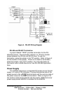
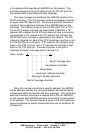
To configure the 485DSS for a typical 2-wire party line network,
set the jumper in the 2W position. Refer to Figure 2 for the jumper
location.
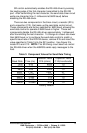
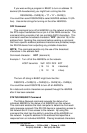
The EIA RS-485 Specification labels data lines with an "A" and
"B" designator. Some RS-485 equipment uses a "+" and "-"
designator. In almost all cases, the "A" line is the equivalent of the "-
" line and the "B" line is the equivalent of the "+" line. See Figure 3
for a wiring example.
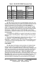
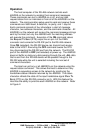
2-Wire Mode
RS-485 allows half-duplex communications of multiple drivers
having a control line for enabling and disabling (tri-stating) their
outputs. When the 485DSS transmits a status reply message to the
Host, the microcontroller will automatically enable the driver before
transmitting the first character of the reply and disable the driver
after the last character of the reply. When the 485DSS is ON
(selected) and the RS-232 device is transmitting data to the Host the
Send Data (SD) control circuit enables and disables the driver. The
485DSS disables the driver when it is not transmitting data to the
Host and listens to (receives) all communications on the network.
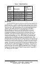
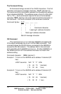
Table 2. RS-232 DTE DB25P Connector Chart
Pin # Signal Description
Signal
Direction of
RS-232 DTE
Port
1
FR GND Frame Ground <------>
2
TD Transmit Data Output
3
RD Receive Data Input
4
RTS Request to Send Output
5
CTS Clear to Send Input
7
SG Signal Ground <------>