


PAGE 30 06 Apr 2000 CH. 5: TIU200/201/202/203
GFK-1819
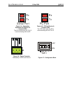
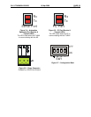
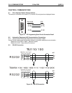
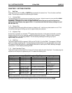
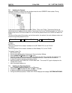
5.5.1 TIU20X Configuration of the RS-485 Port
The configuration bank (shown in Figure 2.23) sets the parameters of the RS-485 port as described in
Table 5.1.
Table 5.1 – Configuration Bank
Switch 1 ON: Pull-up (must be used together with switch 3)
OFF: no Pull-up
Switch 2
ON: 120
Ω
termination
OFF: no termination
Switch 3 ON: Pull-down (must be used together with switch 1)
OFF: no Pull-down
Switch 4 Reserved for future use
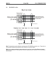
NOTE:
Switch 1 and 3 must be used together. Either both pull-up and pull-down are
used or neither is used.
Pull-up
and
Pull-down
switches are used to increase the signal level on the RS-485 bus. This is useful if
there is a long bus and a significant amount of attenuation is anticipated.
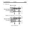
Termination
resistance of 120
Ω
must be placed across each end of the RS-485 bus. With switch 2 ON,
a 120
Ω
resistance is placed across the bus. This should only be used if the TIU050/10X/11X/20X is the
last device at either end of the bus.
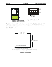
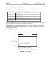
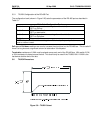
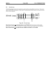
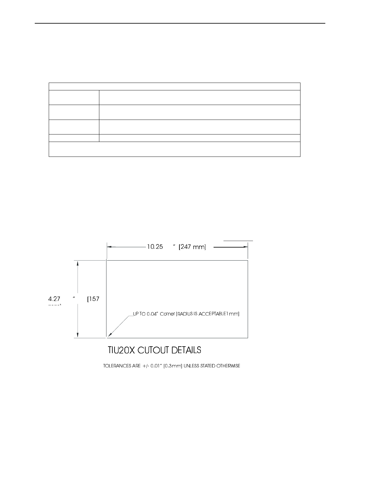
5.6 TIU20X Dimensions
Figure 5.8 – TIU20X Cutout
+0.02
-0.00
+0.5
-0.0
+
0.02
-
0.00