


PAGE 40 06 Apr 2000 CH. 8: NETWORKS
GFK-1819
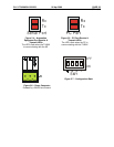
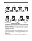
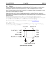
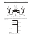
8.5 CAN Wiring Rules
121
Ω
V-
CN_L
SHIELD
CN_H
V+
V-
CN_L
SHIELD
CN_H
V+
V-
CN_L
SHIELD
CN_H
V+
121
Ω
V-
CN_L
SHIELD
CN_H
V+
12-25VDC
+
-
RED
WHT
SHIELD
BLU
BLK
RED
SHIELD
RED
WHT
BLU
BLK
V+
CN_L
V-
SHIELD
121
Ω
CN_H
V+
CN_L
V-
SHIELD
CN_H
RED
WHT
BLU
BLK
121
Ω
V+
CN_L
V-
SHIELD
CN_H
RED
WHT
BLU
BLK
RED
WHT
SHIELD
BLU
BLK
RED
WHT
BLU
BLK
V+
CN_L
V-
SHIELD
CN_H
12-25VDC
+
-
1. Wire the CAN network in a daisy-chained fashion such that there are exactly two physical end-points
on the network.
2. The two nodes at the physical end-points need to have 121 ohm 1% terminating resistors connected
across the CN_L and CN_H terminals.
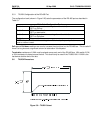
3. Use data conductors (CN_L and CN_H) that are 24 AWG shielded twisted pair for “thin cable” and 22
AWG shielded twisted pair for “thick cable”. They must also have 120-ohm characteristic impedance.
In typical industrial environments, use a Belden wire #3084A (“thin”). Use #3082A (“thick”) for
environments where noise is a concern.
4. Use power conductors (V- and V+) that are 18 AWG twisted-pair for “thin cable” and 15 AWG twisted-
pair for “thick cable”.
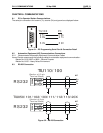
5. Connect the V- power conductor to a good earth ground
at one place only
on the network, preferably
physical endpoints.
6. For a section of cable between two nodes, the cable shield is connected to the cable shield input at
one end of the cable only.
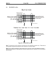
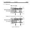
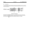
7. A CAN network (without repeaters) is limited to 64 nodes (with 63 cable segments) with a maximum
cable length of 1500 ft.
8. Up to four CAN network segments, which adhere to the above rules, may be connected together
using three CAN repeaters. In this manner, a CAN network may be extended to 253 nodes with a
total cable distance of 6000 ft.
Figure 8.3 – CAN Network Cabling