


72GF-66E
5
ADJUSTMENT PROCEDURES
All adjustments to this chassis, except for focus, are carried out in the service mode.
••
••
• SERVICE MODE
The service mode is provided to enable the engineer to correctly set up the receiver to the CRT fitted in the set.
Note that these adjustments may vary from one receiver to another.
To enter the service mode, carry out the following procedure.
1. Connect a test pattern to the antenna terminal.
2. Tune the receiver to this signal.
3. Turn the receiver off using the mains switch.
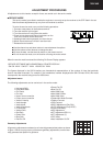
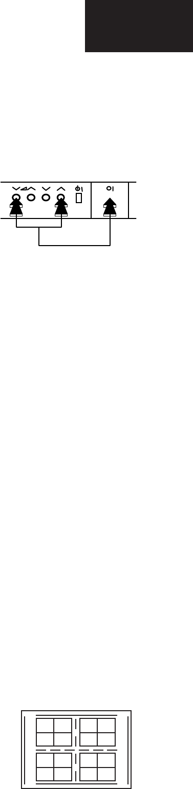
4. Press volume down and channel up buttons on the
front of the receiver at the same time.
5. Keeping these buttons pressed, turn the mains on.
6. When the set starts up it will be in service mode.
7. Release the two buttons.
••
••
• Use the channel up and down buttons to move between the options.
••
••
• Use the volume control buttons to change the data.
••
••
• To store the data, use the stand-by button on the remote control.
••
••
• To exit the service mode, turn the receiver off using the mains switch.
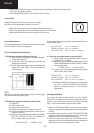
When the service mode is entered the following On Screen Display appears
-SERVICE SOFTWARE AND HEXADECIMAL COUNTER DISPLAY:
SW ON XXXX SW OFF XXXX HOURS ON XXXX
The figures displayed in the XXXX locations are hexadecimal representations of the number of times that particular
function has been executed. For example if the hexadecimal number displayed after SW ON was 0E4A, this would
correspond to the receiver being turned on 3658 times.
Adjustment menu:
The following adjustments can be carried out in the service mode.
CH
4
5
• Horizontal Shift
• East West Width
• Pin Phase
• Pin Amp
• Upper corner correction
• Lower corner correction
• Vertical Linearity
• Vertical angle
• Vertical bow
• Vertical Amplitude
• S Correction
• Vertical Shift
• Red Gain
• Green Gain
• Blue Gain
• Red Cut Off
• Green Cut Off
• Blue Cut Off
• Alter NVM Page
• Alter NVM Position
• Alter NVM Value
• Teletext Mix Mode Contrast
• Teletext Contrast
• OSD Contrast
• DVCO Adjustment (Only PAL)
• DVCO Adjustment (Only NTSC)
• Luma croma delay
• AGC Adjustment
• AFT Adjustment (BG-I-L)
• AFT Adjustment (L’)
• OPC Value
• Auto Installation On/Off
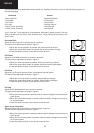
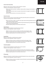
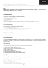
Geometry Adjustments
All geometry adjustments are based on an internally generated test pattern as shown
in figure 1. When carrying out any of the above geometry adjustments, use the inter-
nally generated test pattern for guidance.
Fig.1