


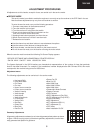
72GF-66E
8
Colour Adjustments
The following adjustments should only be carried out when
the CRT, IC801 or IC801 are replaced.
G2, Cut Off and Gain Adjustments
1. Follow the procedure below to set the G2
1.1 Tune the set to the output of a signal generator
(cross hatch pattern).
1.2 In the user menu, set contrast to 80/100 and
brightness to 40/100.
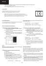
1.3 Connect the oscilloscope to the red cathode and
adjust G2 to read 135V on the sensor pulse as
in the drawing:
NOTE:
Oscilloscope should be adjusted for vertical TV field trigger
and synchronized with video signal.
2. Follow the procedure below to set the Cut Off.
2.1 Adjust G2.
2.2 Tune a white card.
2.3 Adjust colour to minimum.
2.4 Position colorimeter in the centre of screen.
2.5 Adjust brightness and contrast to obtain a lumi-
nance of ≈20 NITS.
2.6 Operate in Service Mode and select location RED
CUT OFF, GREEN CUT OFF and BLUE CUT
OFF, to obtain colour coordinates:
X=0.290 ± 0.015 Y=0.300 ± 0.015
To increase press volume-up button and to decrease press
volume down button.
RED CUT OFF alter «X» coordinate.
GREEN CUT OFF alter «Y» coordinate.
BLUE CUT OFF alter «X» and «Y» coordinate.
3. Follow the procedure below to set the GAIN.
3.1 Using brightness and contrast buttons, select a
luminance of ≈120 NITS.
3.2 Operate in Service Mode and select location RED
GAIN, GREEN GAIN and BLUE GAIN, to obtain
colour coordinates:
X=0.290 ± 0.015 Y=0.300 ± 0.015
To increase press volume-up button and to decrease
press volume down button.
RED CUT OFF alter «X» coordinate.
GREEN CUT OFF alter «Y» coordinate.
BLUE CUT OFF alter «X» and «Y» coordinate.
3.3 Exit Service Mode and check colour coordinates
«X» and «Y» at 20 and 120 NITS. It may be nec-
essary to repeat procedure 2 and 3 of Colour
Adjustments.
Changing NVM Data
To change the data contained within the Non Volatile
Memory, it is necessary to first select the page the data is
stored in, then the position and finally to change the data
itself. The procedure below outlines this process.
1. While on ALTER NVM PAGE, use the volume up/down
buttons to change this data (data is shown in hexadecimal
format).
2. Press the channel up button and ALTER NVM POSITION
appears, use the volume up/down buttons to change this
data (data is shown in hexadecimal format).
3. Press the channel up button and ALTER NVM VALUE
appears, use the volume up/down buttons to change this
data (data is shown in hexadecimal format).
• When the volume down button is pressed the top and bottom scanning decreases and
the centre scanning increases.
• Press the stand-by button on the remote control to store.
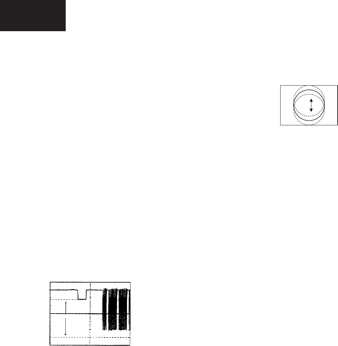
Vertical Shift
Adjust the Vertical Shift so that the picture is centred.
The effect of this adjustment is shown in figure 13.
• When the volume up button is pressed, the picture moves up.
• When the volume down button is pressed, the picture moves down.
• Press the stand-by button on the remote control to store.
Fig.13
135 V
CH1 gnd