


5
2-6 Accessory Interface
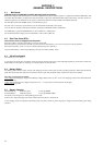
The table explains what kind of pins the phone supplies to the different accessories.
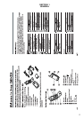
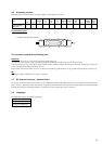
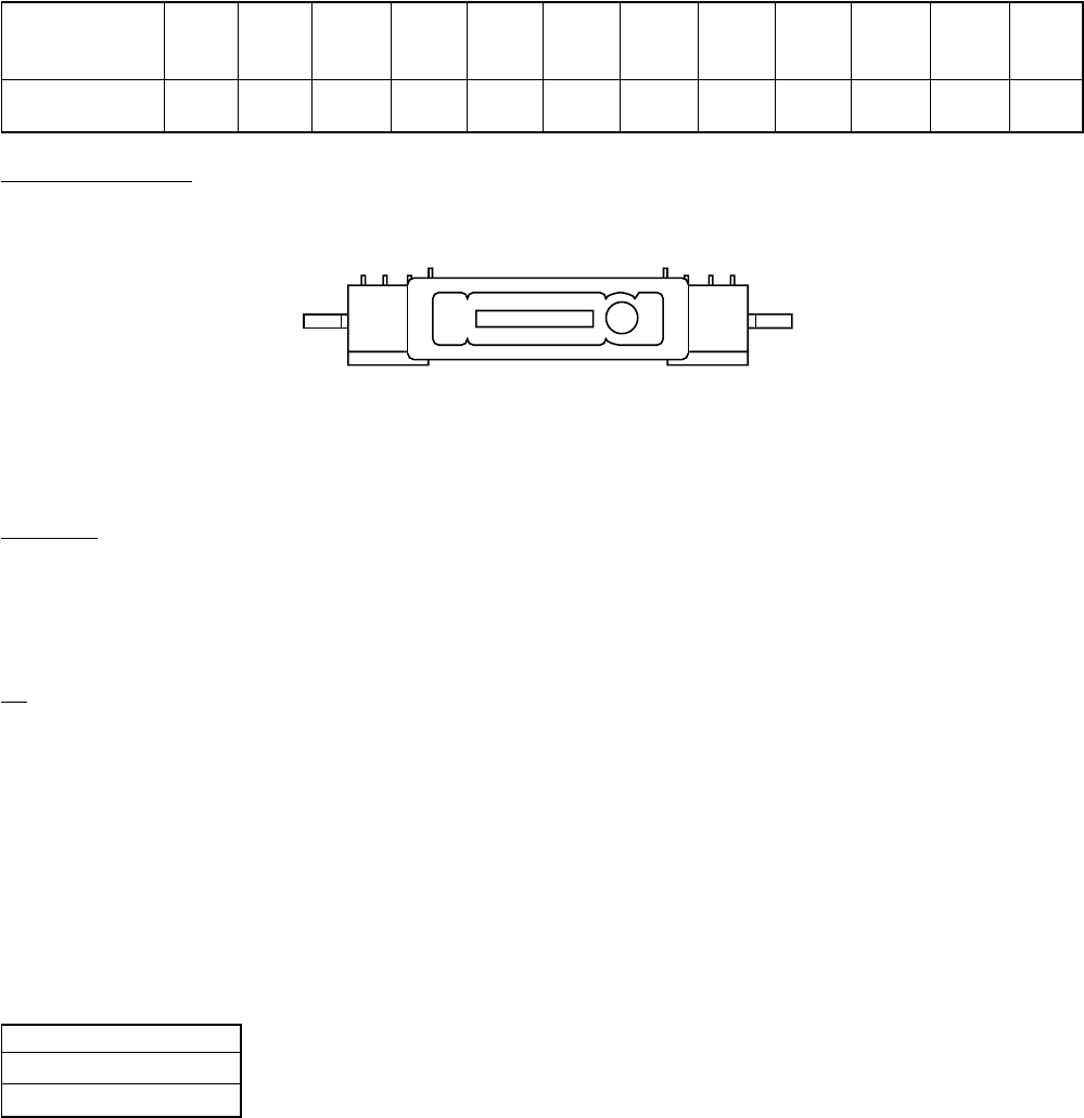
I/O connector layout
The connector comprises the following pins:
Detection:
The detection of accessory is done by the charge pin and the detect pin.
Any accessory with an active charge will wake up the phone, indicating the battery icon but can not be operated.
The insertion and removal of the charger (Cigar Lighter Charger, Desktop-Charger, AC-Charger) is detected via polling. To reduce the
power consumption the polling can take up to 5 sec.
The insertion and removal of other accessory is detected via an Interrupt. This detection is only possible when the phone is powered up.
ID:
The ID pin indicates what kind of accessory is connected.
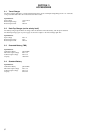
2-7 RF Antenna Connector / Antenna Switch
To connect an external antenna for accessory use, the CMD-Z28 contains a stable RF connector with an integrated mechanical switch.
This connector is placed on the I/O connector. The integrated mechanical switch switches between the helix antenna and the external RF
antenna connection. The switching criterium is mechanical pressure from the RF accessory connector.
2-8 Languages
The CMD-Z28 supports the following languages:
• English
• Chinese (Simplified)
• Chinese (Traditional)
GND Charge ACC_ Audio Audio ACC ACC TX RX AGND RF RF
Pins power IN Out ID Detect (OUT) (IN) GND OUT
18 1/2 3 14 13 11 6 9 10 12 19/22 20
Travel charger
√√
(QN-2TC)
Connector view from base of phone
117
218