10
How to deploy the Dell M8024 family of switches in a Cisco Nexus network
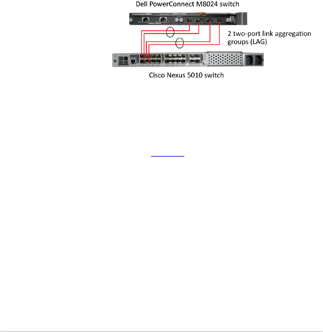
from between the two groups created earlier. The traffic from the
blade servers that are connected to internal ports belonging to
Group 1 will use LAG, including those external ports that are part
of that group. This applies to the blade servers in Group 2 as well.
Figure 5 illustrates the completed configuration for Scenario 4.
Figure 5: Graphic representation of Scenario 4.
Scenario 5: Adding VLANs in a multi-AG configuration
In this section, we provide an overview of adding VLANs in a multi-AG
configuration, which combine the advantages of virtual network
administration with physical network separation. We provide detailed
instructions in Appendix A.
1. On the Dell PowerConnect M8024 switch, enter the Port
Configuration screen, and change the group ID of ports to Group 2
(we changed ports 1/xg9-1/xg16 and ports 1/xg23-1/xg24 to
Group 2).
2. Enter the Internal Port VLAN configuration screen, select a port,
and add several tagged VLANs (we changed port 1/xg1 to include
VLANs 101-102 and port 1/xg9 to include VLANs 103-104).
3. On the Cisco Nexus 5010 switches, create two two-port channel
groups with LACP enabled. Make sure that the two port channels
include the VLANs you configured earlier (we configured VLANs
101-102 for the first port channel and VLANs 103-104 for the
second port channel).
4. Connect the cables. The Dell PowerConnect M8024 switch will
automatically make two two-port LAGs, separating the traffic
from between the two groups created earlier, while allowing for
further segregation through VLANs.
Figure 6 illustrates the completed configuration for Scenario 5.


