


4. Product and components
2 1 3 2
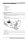
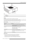
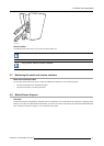
Image 4-3
Base Unit
1 USB port
2 Status LED strip
3 Standby button
Table 4- 3
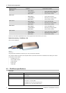
USB port
The USB port is used to update the software of both the Base Unit and the Buttons.
When plugging in the Button into the Base Unit, the Button is paired to the Base Unit. The Base Unit checks whether the Button’s
software and firmware are up to date. If not, the Base Unit updates the software and/or firmware.
To update the Base Unit software, download the latest version of the software from the Barco website. Copy the file on a USB stick
and plug it into the USB port of the Base Unit. Follow the progress and instructions on the display.
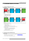
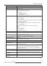
Status LED strips
The color of the LEDs at the front of the Base Unit
give information on the status of the system.
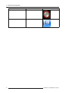
LEDs behavior Explanation
static red
• receiving content from the Buttons and streaming towards the display.
• pairing and software update of the Button is done. You can now unplug the
Button from the Base Unit.
• during the first phase of the Base Unit boot process.
blinking white
• system is starting up (during the second phase)
• Button pairing is in progress
• software update of the Base Unit
slow blinking white
• standby mode (i.e. muting the display output)
static white
• awake and ready (i.e. showing the wel
come message on the display)
• pairing is done
red blinking
• an error occurred
Standby button
The button at the front of the Base Unit has a power on/off function and a standby function.
• When the system is awake, a short push triggers the system to go into standby mode.
• When the system is in standby mode, a short push triggers the system to wake up.
• When the system is powered on, a long push makes the system to shut down and power off.
• When the system is shut down, a long push or short push triggers the system to start up.
R5900006 CLICKSHARE 04/12/2013
17