


3-6
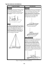
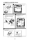
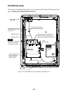
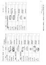
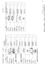
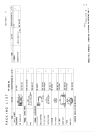
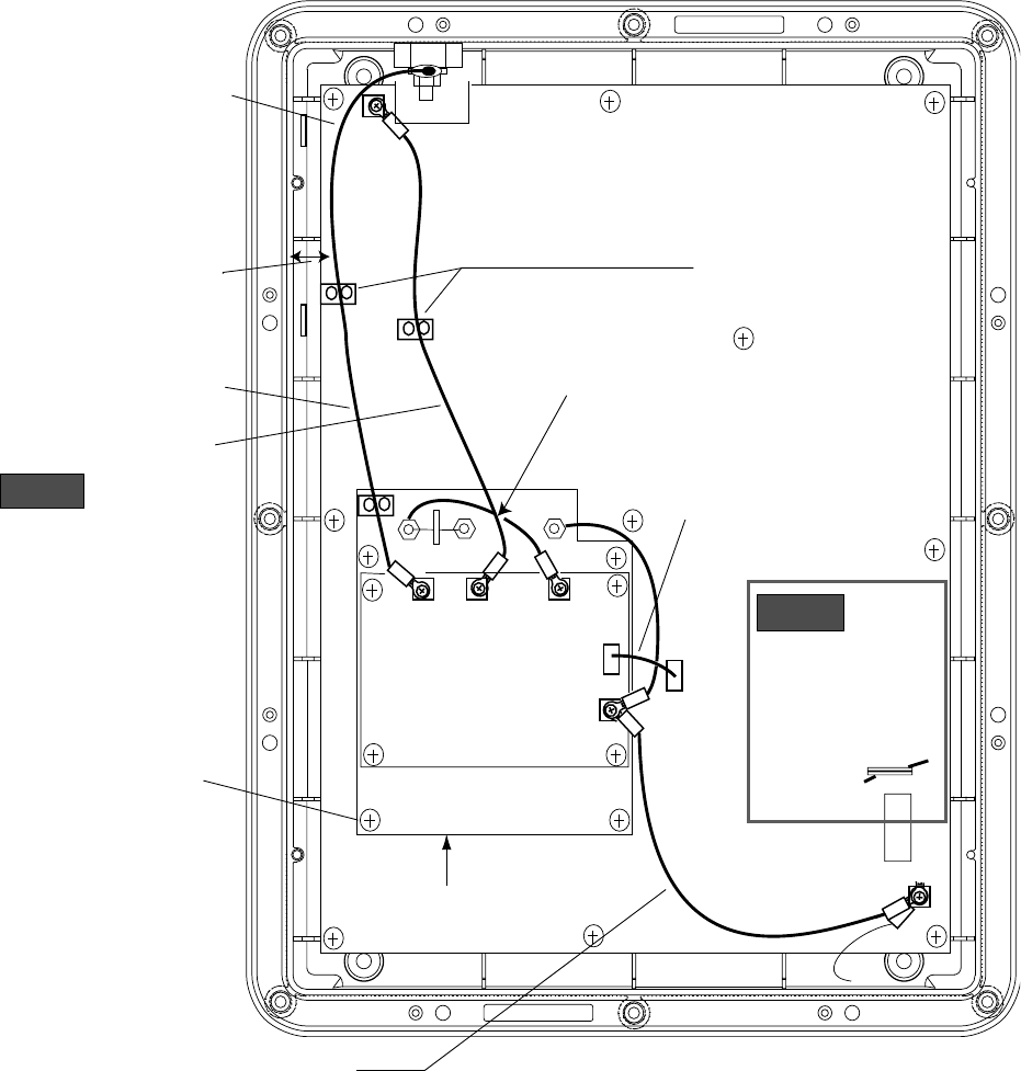
3.9 Dummy Load
The dummy load enables testing of the two-tone alarm. Install the board following the figure
below. CHANGE SYSTEM SETTING 9917 to 1.
J
TX
OUT
TX
IN
E
TB2
TB1
TB3
TB4
E
TB3
TB4
J1
J2
ANT
NOTICE
NOTICE
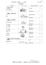
W3 WIRE ASSY.
W5
WIRE ASSY.
W6
WIRE ASSY.
W4 WIRE ASSY.
Separate wire assemblies
W3 and W4 more than
15 mm from each other.
Fasten wire with cable tie.
Gap between inner wall
and wire should be more
than 15 mm.
Do not route
wires within
this area.
Fasten dummy load
assy. to shield case
with four existing
screws (4 pcs.).
W4 should not touch
TB4 or W3.
Separare these wires: Bend crimp-on
lug attached to TB1 upward; bend
crimp-on lug attached to TB3 downward.
DUMMY CONT
BOARD 05P0670
DUMMY
DUMMY LOAD ASSY.
Figure 3-6 COUPLER board, installation of dummy load