


- 60 -
3. TECHNICAL BRIEF
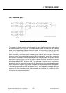
3.24 DCXO
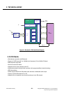
The transceiver contains a fully integrated 26MHz digitally controlled crystal oscillator (DCXO) with
three outputs for the system clock, one output for the GSM baseband and two additional for other
subsystems (GPS, Bluetooth, etc.). The only external part of the oscillator is the crystal itself. The
overall pulling range of the DCXO consists of eight subranges. The subrange closest to the ‘0ppm’ at
the middle AFC-value is selected during the calibration process in the mobile’s production and is used
for the rest of the lifetime. The frequency tuning is performed along the selected subrange by
programming the frequency control word (XO_TUNE) via the three wire bus (“3Wbus”).
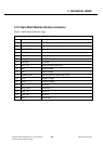
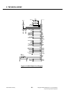
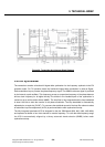
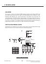
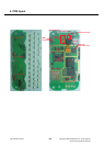
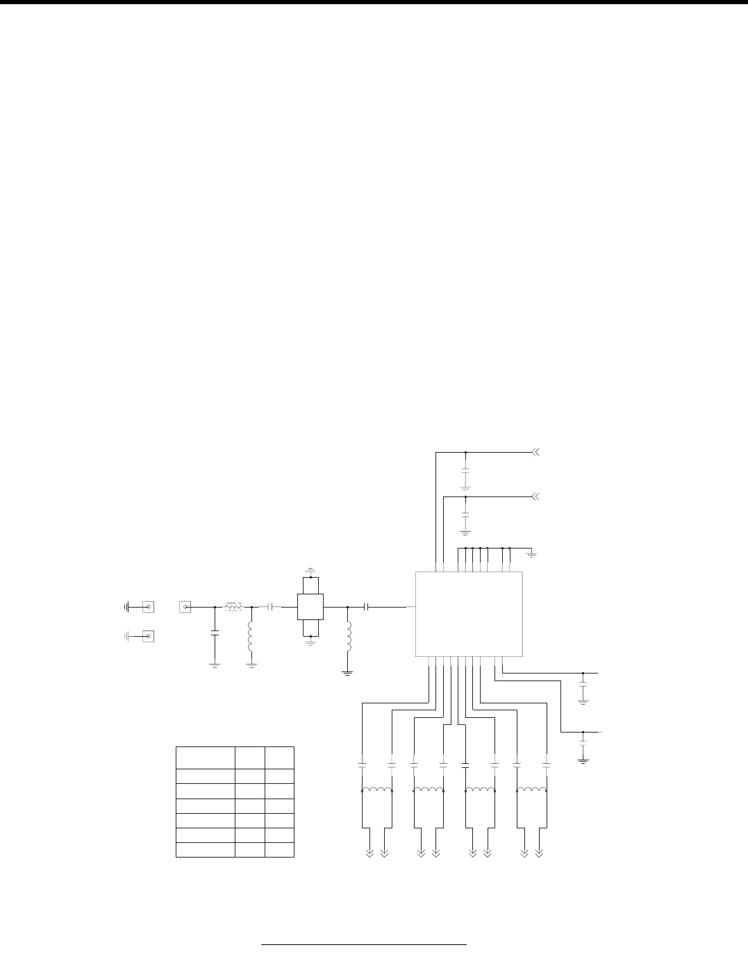
3.25 Front End Module control
Implemented in the Transceiver are two outputs for direct control of front end modules with two logic
input pins to select RX- and TX-mode as well as low- and high band operation.
LGE Internal Use Only
Copyright © 2008 LG Electronics. Inc. All right reserved.
Only for training and service purposes
PIN 14
DCS1800
L
L
L
GSM900
L
PCS1900
L
EGSM900 RX
GSM850
L
DCS1800 RX
L
H
RF
GSM850_EGSM TX
GSM850 RX
L
VC2
DCS_PCS TX
PIN 13
H
VC1
PCS1900 RX L
L
5.1nH
L609
C645
3.9p
PAD601
3.9p
C646
3.3p
C648
PAD600
C622
33p
0.5p
C634
0
R608 C631
5p
22nH
L607
33p
C627
12nH
L605
DNI
C641
13
GSM850_900TX
GSM900RX1
3
4
GSM900RX2
NC1
19
NC2
20
16
VC1
VC2
10
17
ANT
GND1
9
GND2
12
14
GND3
GND4
15
18
GND5
GSM1800RX1
5
6
GSM1800RX2
GSM1800_1900TX
11
7
GSM1900RX1
GSM1900RX2
8
GSM850RX1
1
2
GSM850RX2
NA
L604
LMSP43NA-782
U601
2.5p
C643 C644
2.5p
PAD602
5.6p
C650
3.3p
C647
22p
C632
5.6p
C649
L608
5.6nH
L610
18nH
CN600
MM8430-2600RB3
3
GND1
4
GND2
GND3
5
GND4
6
1
IN
OUT
2
0.75p
C633
VC1
VC2
GSM850_RXP
GSM850_RXN
GSM900_RXN
GSM900_RXP
DCS1800_RXP
DCS1800_RXN
PCS1900_RXN
PCS1900_RXP
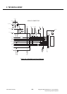
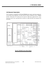
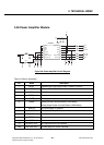
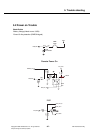
Figure 27. FEM Circuit Diagram