


Installation
42
©
2001 Nokia Mobile Phones. All rights reserved.
Installation
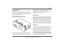
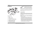
Cable connections
1. Handset
2. Handsfree microphone
3. Handsfree loudspeaker
4. 12V car battery + (with 3A fuse), 2 x red
5. 12V car battery - (with 3A fuse), 2 x black
6. Car ignition sense (with 1A fuse), blue
7. Car radio mute connector, yellow
8. Car antenna motor control, orange
9. Car backlight dimming signal, grey
10. Phone audio line-out, black cable
The phone audio line-out has to be con-
nected to the car radio line-in. It delivers
two differencial audio signals, each one sur-
rounded by a mass. At a load impedance >
1kOhm, the nominal level is 70 mVrms, the maximum level 2000
mVrms. Check with your car radio dealer to ensure that your
specific radio line-in is compatible with your phone equipment.
Note: The SIM card and antenna represented here are not in-
cluded in the package.
Recommendations
Warning! Only qualified personnel should service the car phone
or install the car phone in a vehicle. Faulty installation or service
may be dangerous and may invalidate any warranty which may
apply to the unit.
Note: When installing the car kit in Australia and New Zealand,
the 6090 should be installed in accordance with AS/NZS 4346.
• Microphone installation
The recommended position for the microphone should be the
top of the A-pillar or, alternatively, near the back mirror in
the middle of the car. The microphone should be pointed in
the direction of the driver‘s mouth with a optimum distance
of 30 cm. Streams of fresh air should not be directed at the
microphone and the microphone cable should not be laid in
the ventilation system. Use the provided soft material to con-
nect the HF microphone to the A-pillar in order to avoid any
noise coupling from the car to the microphone.