


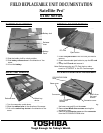
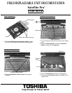
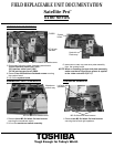
MEMBRANE SWITCH REMOVAL
1. Remove three M2.5x4 black flat head screws
securing the membrane switch.
2. Lift out the membrane switch assembly.
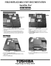
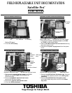
FIELD REPLACEABLE UNIT DOCUMENTATION
6100 Series
TOSHIBA
Tough Enough for Today’s World.
1. Remove two M2.5x4 black flat head screws
securing the left and right speakers.
SPEAKERS REMOVAL
Satellite Pro
TM
M2.5x4 black flat head screws
Membrane
switch assy
Left and right
speakers
M2.5x4 black flat head screws
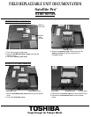
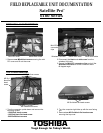
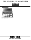
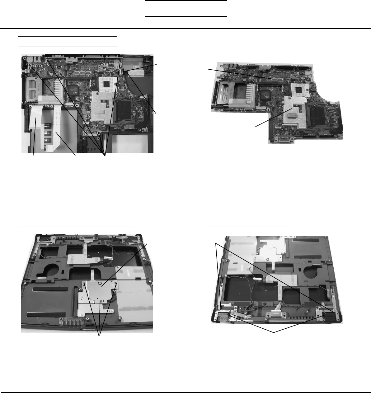
3. Disconnect following cables from the system board:
-Sound interface cable from PJ302
-SD interface cable from PJ365
-DC-IN jack harness from PJ8800
4. Remove four M2.5x4 black flat head screws securing
the system board.
5. Lift out the system board.
M2.5x4 black flat head screwsSDcable
Sound cable
DC-IN jack
harness
PJ8800
SYSTEM BOARD REMOVAL
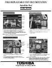
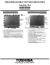
6. Remove the video chip heat sink plate assembly
from the system board.
System
board
NOTE: When re-installing the heat sink plate assembly,
make sure that a 0.2g silicone grease is applied
to the video controller IC(IC11).
Heat sink
Plate assy