


TOSHIBA
Tough Enough for Today’s World.
FIELD REPLACEABLE UNIT DOCUMENTATION
6100 Series
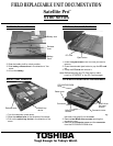
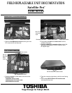
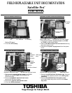
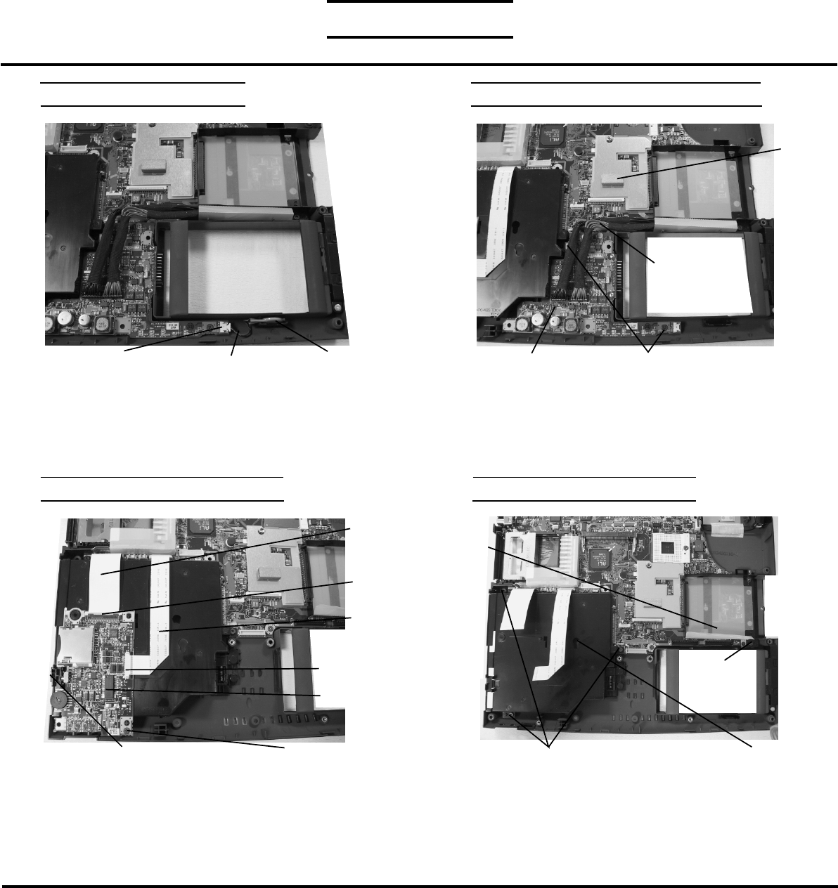
1. Remove one M2.5x6 black flat head screw securing
the HDD guide assembly and lift out the HDD guide
assembly.
2. Remove three M2.5x6 black flat head screws
securingthe select bay cover and lift out the select
bay cover.
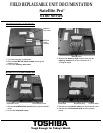
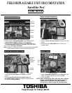
SYSTEM BOARD REMOVAL SD/SOUND BOARD REMOVAL
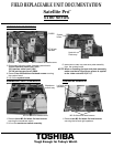
1. Disconnect the sound interface cable from PJ103
and the SD interface cable from PJ150 on the
SD/Sound board.
2. Remove one M2.5x4 black flat head screw
securing the SD/Sound board.
3. Remove the wireless LAN switch button.
4. Lift out the SD/Sound board.
Satellite Pro
TM
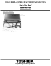
1. Disconnect the power supply harness from PJ850
and PJ851 on the system board.
2. Remove two M2.5x4 black flat head screws securing
the power supply board.
3. Disconnect the power supply board from the system
board.
POWER SUPPLY BOARD REMOVAL
System
board
Power supply board
M2.5x4 black flat head screws
SD
interface
cable
M2.5x4 black flat head screw
Sound
Interface
cable
SD/Sound board
PJ2150
PJ2103
M2.5x6 flat
head black
screw
M2.5x6 black flat head screws
Select bay cover
Power supply
harness
Wireless LAN switch button
HDD guide
assy
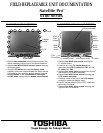
RTC BATTERY REMOVAL
1. Disconnect the RTC harness from PJ5 on the
Battery/LED board.
2. Lift out the RTC battery.
RTC Battery
RTC harness
PJ5