


TOSHIBA
Tough Enough for Today’s World.
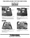
FIELD REPLACEABLE UNIT DOCUMENTATION
6100 Series
Satellite Pro
TM
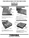
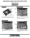
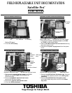
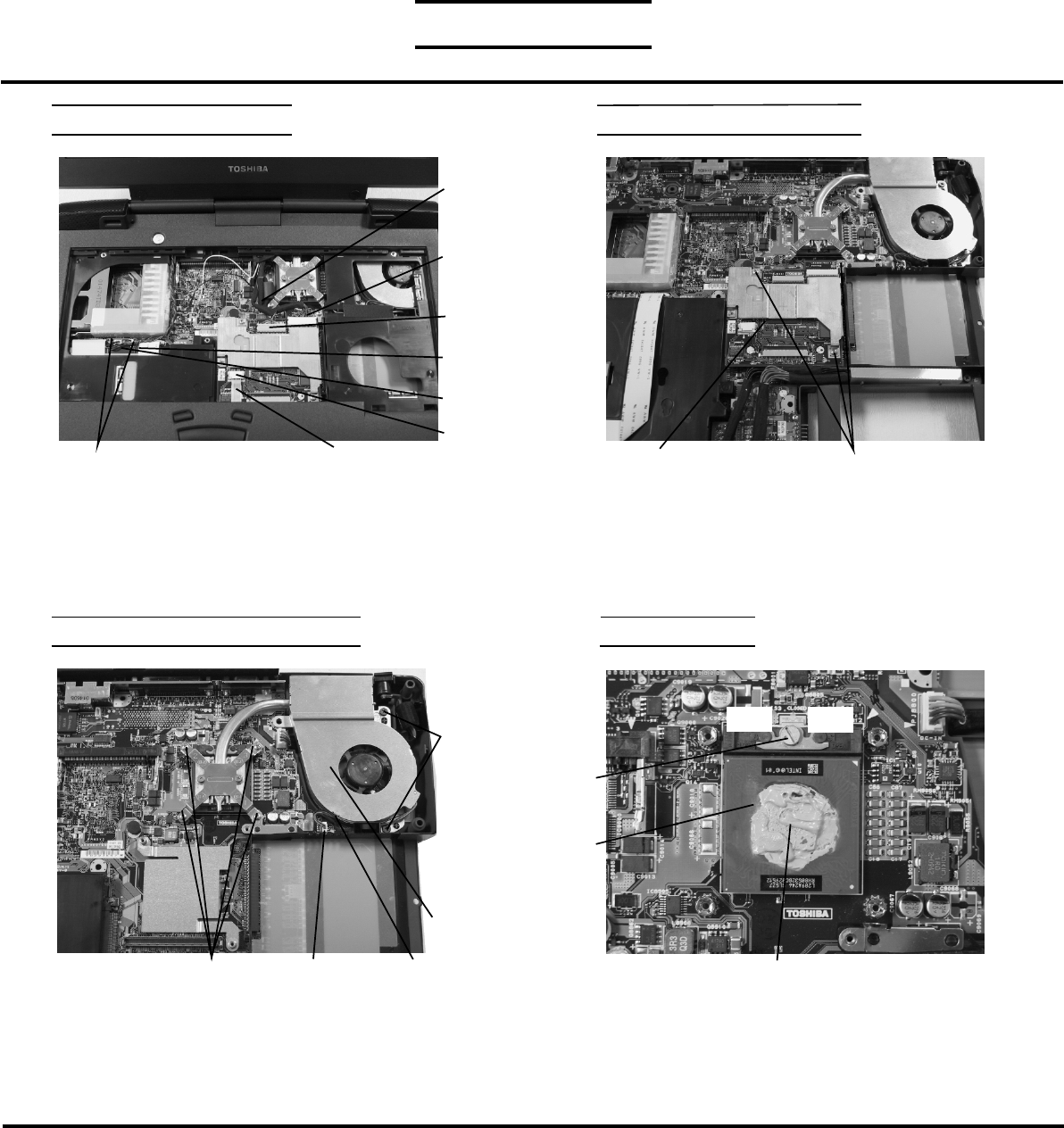
4. Disconnect the left speaker cable from PJ310 and the
right speaker cable from PJ311 on the top board.
5. Disconnect the LCD/FL harness from PJ5002/5001 and
the IPS membrane switch from PJ122 on the video board.
6. Lift out the top cover assembly.
Note: When re- installing the top cover, ensure that the bluetooth
coaxial cable is properly routed to the Bluetooth slot.
TOP COVER REMOVAL
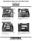
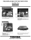
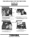
COOLING MODULE REMOVAL
1. Disconnect the fan cable from PJ8770 on the top
board.
2. Remove two M2.5x6 black flat head screws and
four M2x4 brass screws securing the cooling module.
3. Lift out the cooling module.
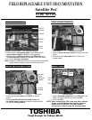
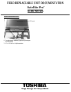
CPU REMOVAL
1. Insert a flat head screwdriver in the CPU lock and
rotate it counter-clockwise to unlock the CPU.
2. Lift out the CPU.
NOTE: When installing the CPU, make sure that a silicone
grease is applied before attaching the heat sink.
Please refer to FSB-200112 for the complete
procedures on how to apply the silicone grease.
LCD/FL
harness
Left/Rigth speaker cable
PJ310
PJ302
PJ5002
IPS membrane switch
PJ122
PJ5001
PJ8770
Cooling
module
M2X4 brass screws
Fan cable
M2.5x6
black
flat head
screws
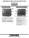
VIDEO BOARD REMOVAL
1. Remove three 2x4 brass screws securing the video
board.
2. Disconnect the video board from PJ100 on the
system board.
Video board M2x4 brass screws
CPU
lock
Silicone grease
CPU
Open
Close