24 PowerMonitor 1000 Unit
Rockwell Automation Publication 1408-IN001E-EN-P - September 2013
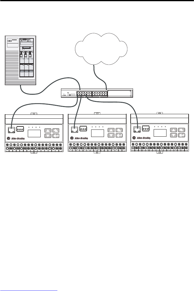
Typical Ethernet connections are shown in this diagram.
Ethernet Network Typical Connections
Ground the PowerMonitor 1000 Unit
In solid-state systems, grounding helps limit the effects of noise due to electromagnetic
interference (EMI). Run the ground connection from the ground terminal of the power monitor
to the ground bus or other low-impedance earth ground prior to connecting the control power
or any other connections. Use 0.21 mm
2
(14 AWG) wire.
Grounding is also required in the voltage and current sensing circuits to limit the maximum
voltage to ground for safety. All grounds should be made to a common ground bus or terminal.
Set Up the PowerMonitor 1000 Unit
Although the power monitor ships from the factory with default settings, you need to configure
it for your particular requirements. You may configure the power monitor using the LCD, the
HyperTerminal communication tool, a Web interface, or other software. This section describes,
in general, methods for setting up the power monitor.
Refer to Features on page 39
for configuration specifics related to various functions.
PowerMonitor 1000
EtherNet/IP
ACT LNK
STATISRS-485
RS-485
+ - SHLD
RX TX Mod Net
PowerMonitor 1000
EtherNet/IP
ACT LNK
STATISRS-485
RS-485
+ - SHLD
RX TX Mod Net
PowerMonitor 1000
EtherNet/IP
ACT LNK
STATISRS-485
RS-485
+ - SHLD
RX TX Mod Net
Computer
LAN/WAN
Ethernet Switch
UTP Patch Cable (typical)
PowerMonitor 1000 Unit PowerMonitor 1000 Unit PowerMonitor 1000 Unit


