Page 3-4 400 SERIES INSTALLATION MANUAL
Page Rev L P/N 190-00140-02
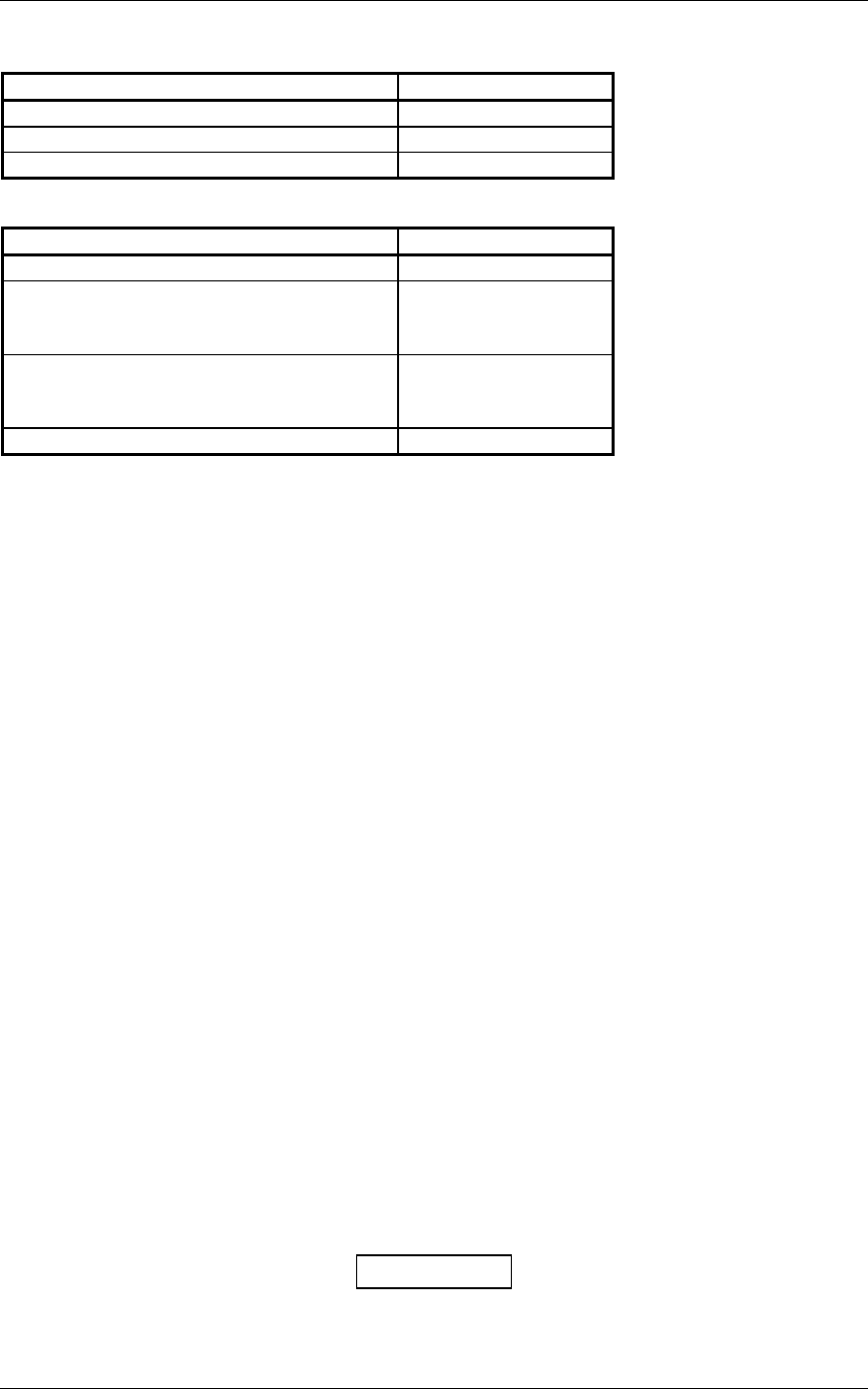
3.2 DATA BASE OPTIONS
ITEM GARMIN P/N
DATA CARD, WORLD WIDE 010-10201-00
DATA CARD, AMERICAS 010-10201-01
DATA CARD, INTERNATIONAL 010-10201-02
3.3 MISCELLANEOUS OPTIONS
ITEM GARMIN P/N
CONNECTOR, BNC, MALE, CLAMP 330-00087-00
LOW-LOSS AVIATION ANTENNA
EXTENSION CABLE WITH RIGHT
ANGLE BNC CONNECTOR, 15 FT.
320-00003-00
LOW-LOSS AVIATION ANTENNA
EXTENSION CABLE WITH RIGHT
ANGLE BNC CONNECTOR, 30 FT.
320-00003-02
GPS 1.57542 GHz NOTCH FILTER 330-00067-00
3.4 INSTALLATION ACCESSORIES REQUIRED BUT NOT PROVIDED
The following installation accessories are required but not provided:
COM Antenna: (GNC 420 and GNS 430 Only) Shall meet TSO C37() and C38(). Broad band, 50
Ω, vertically polarized with coaxial cable
VOR/LOC Antenna: (GNS 430 Only) Shall meet TSO C40() and C36(). Broad band, 50 Ω,
horizontally polarized with coaxial cable
Glideslope Antenna: (GNS 430 Only) Shall meet TSO C34(). Broad band, 50 Ω, horizontally polarized
with coaxial cable or low-loss splitter used with the VOR/LOC antenna
Headphones: (GNC 420 and GNS 430 Only) 500 Ω nominal impedance
Microphone: (GNC 420 and GNS 430 Only) Low impedance, carbon or dynamic, with
transistorized pre-amp
3.5 ANTENNA INSTALLATION
For the COM, VOR/LOC, and Glideslope antennas, follow the manufacturers’ instructions.
The remainder of this section applies to the GPS antenna. The GA 56 antenna outline and footprint
dimensions are shown in Figure 3-2, page 3-9. Also refer to 190-00094-00 GA 56 Antenna Installation
Instructions.
1. Using the backing plate as a template, mark the location of the mounting holes and the through
hole for coaxial cable. Drill or punch the holes.
2. The antenna installation must provide adequate support for the antenna, considering a
maximum drag load of 5 lbs. for the GA 56 antennas (at subsonic speed). Install a doubler
plate to reinforce thin-skinned aircraft. Observe guidelines for acceptable installation practices
as outlined in AC 43.13-2A.
Seal the antenna and gasket to the fuselage using a good quality electrical grade sealant. Use caution to
insure that the antenna connector is not contaminated with sealant. Insure that the mounting screws are
fully tightened and that the antenna base is well seated against the gasket.
CAUTION
Do not use construction grade RTV sealant or sealants containing acetic acid. These
sealants may damage the electrical connections to the antenna. Use of these type sealants
may void the antenna warranty.


