Page 5-8 400 SERIES INSTALLATION MANUAL
Page Rev L P/N 190-00140-02
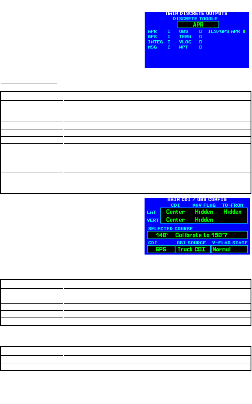
5.2.9 MAIN DISCRETE OUTPUTS Page
Select the MAIN DISCRETE OUTPUTS Page (see Figure
5-11). This page allows you to verify the operation of any
external annunciators and switches that are present in the
installation.
DISCRETE TOGGLE
Selection Verify That:
APR
The APR annunciator is active and inactive as selected on this page.
GPS
The GPS source select annunciator is active and inactive as selected on this
page.
INTEG
The INTEG annunciator is active and inactive as selected on this page.
MSG
The MSG annunciator is active and inactive as selected on this page.
OBS
The OBS annunciator is active and inactive as selected on this page.
TERM
The TERM annunciator is active and inactive as selected on this page.
VLOC
The VLOC source select annunciator is active and inactive as selected on this
page.
WPT
The WPT annunciator is active and inactive as selected on this page.
ILS/GPS APR
The ILS/GPS APPROACH output is active and inactive as selected on this
page (NOTE: This output is connected to the autopilot ILS ENGAGE input,
not to an annunciation, and therefore this is for bench testing purposes only).
5.2.10 MAIN CDI/OBS CONFIG Page
Select the MAIN CDI/OBS CONFIG Page (see Figure 5-
12). This page allows you to verify the MAIN CDI
outputs, both lateral (LAT) and vertical (VERT), and
verify and calibrate the MAIN OBS input. Using the
controls on the 400 Series unit front panel, make the
selections below and verify the interfaces as appropriate:
CDI (LAT/VERT)
Selection Verify That:
Max left/up
The CDI is “pegged” to the left/up.
Full left/up
The CDI is deflected full scale to the left/up.
Center
The CDI is centered.
Full right/down
The CDI is deflected full scale to the right/down.
Max right/down
The CDI is “pegged” to the right/down.
NAV FLAG (LAT/VERT)
Selection Verify That:
Hidden
The LAT/VERT flag is hidden.
In view
The LAT/VERT flag is in view.
Figure 5-11.
MAIN DISCRETE OUTPUTS Page
Figure 5-12.
MAIN CDI/OBS CONFIG Page


