400 SERIES INSTALLATION MANUAL Page 5-7
P/N 190-00140-02 Page Rev L
OFFSET
Adjusts the lighting level up or down for any given input level. This field has a range of 0 (zero) to 99,
and is set to 50 at the factory. This may also be used to match lighting curves with other equipment in the
panel.
PHOTO TRANS % - (Photocell Transition Percentage)
When a lighting bus is used to control the lighting of the
display (see Figure 5-7), this parameter sets the point on
the lighting bus control below which the display brightness
tracks the 400 Series unit’s photocell. This field has a
range of 0 (zero) to 99, and is set to 25 at the factory.
PHOTO SLP/OFFST - (Photocell Slope/Offset)
These fields are equivalent to the SLOPE/OFFSET fields
described above, with the exception that they only control
the display lighting characteristics when the lighting bus control is below the level specified in the PHOTO
TRANS % field. Both fields have a range of 0 (zero) to 99, and are set to 50 at the factory.
CONTRAST
If contrast isn’t acceptable, place unit in Normal Mode. On
the AUX menu SETUP page 2, highlight DISPLAY and
press ENTER. The DISPLAY page is shown (see Figure
5-8). Confirm that CONTRAST MODE is “Auto”.
Highlight CONTRAST LEVEL and adjust to best
viewable color. Press ENTER to confirm change.
NOTE
Note: Leave CONTRAST MODE in “Auto”.
5.2.7 DATE/TIME SETUP Page
Select the DATE/TIME SETUP Page (see Figure 5-9).
Very infrequently, it may be desirable to set the date and
time of the 400 Series unit to aid in acquiring a GPS
position. Configuration mode is the only means by which
the date and time for the 400 Series unit may be adjusted.
Note that the time must be UTC time, and that the UTC
date may be different from the date in the local time zone.
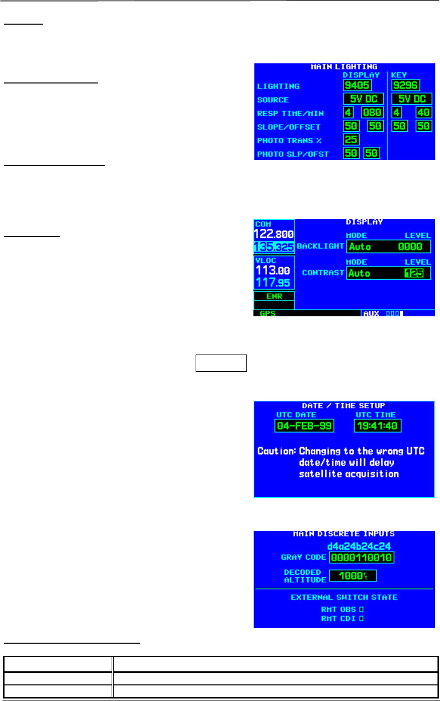
5.2.8 MAIN DISCRETE INPUTS Page
Select the MAIN DISCRETE INPUTS Page (see Figure 5-
10) if the encoding altimeter input is used. Verify that the
DECODED ALTITUDE field indicates the correct
altitude.
EXTERNAL SWITCH STATE
Selection Verify That:
RMT CDI
The box is filled in while a remote CDI source select switch is pressed.
RMT OBS
The box is filled in while a remote OBS switch is pressed.
Figure 5-7. MAIN LIGHTING Page
(Display Lighting from Lighting Bus)
Figure 5-8.
DISPLAY Page (AUX Group)
Figure 5-9.
DATE/TIME SETUP Page
Figure 5-10.
MAIN DISCRETE INPUTS Page


