Getting Started With the Web Interface
23
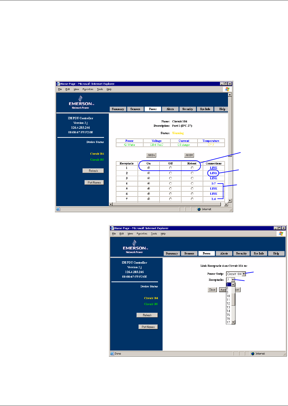
Link the Controls of Two Receptacles
Two receptacles may be linked for simultaneous control. The receptacles may be on the same power
strip or on two different power strips. When two receptacles are linked, the Connections column dis-
plays the link as x:y, where x is the OpenComms EM serial port number (1 or 2) and y is the number
of the linked receptacle. In the example below, receptacles 4 and 7 on serial port 1 are linked, shown
in the Connections column as 1:7 and 1:4.
Once linked, both receptacles will be turned on, off or rebooted at the same time when you click on the
On, Off or Reboot button for either receptacle in the Power Data window, shown below.
Figure 8 Linking receptacles
To link two receptacles:
• In the right side of the
Power Data window, click on
LINK in the Connections
column for either receptacle,
as shown in Figure 8.
•The right side of the window
displays the selected recep-
tacle—Receptacle 4 on Port 1
in the example at right.
Click on the down arrow of
the Power Strip list box and
select the serial port.
• Click on the Receptacle box
and select the number of the
receptacle to be linked.
•Click Apply to accept the
changes. (Or click Reset to
cancel.)
To break the link:
• In the right side of the Power Data window, click on the x:y entry in the Connections column for a
receptacle—for example, click on 1:7 for Receptacle 4 in Figure 8.
• In the link window (Figure 9), click on the down arrow of the Power Strip list box and select
None.
•Click Apply to accept the changes. (Or click Reset to cancel.)
Linked
receptacles
4 & 7 (Port 1)
LINK
On, Off, Reboot
buttons
Power strip
port
Receptacle
to be linked
Figure 9 Link window


