


2-5
Installing an ANIM
Installing an ANIM
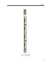
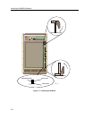
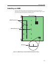
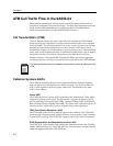
Figure 2-3 shows the location of the 4 motherboard connectors, and the 16
standoff screws for the ATM Network Interface Modules (ANIMs). Figure 2-3 also
shows the location of the Module Card DIP Switch.
Figure 2-3. ANIM Connector Locations and Module DIP Switch Location
ANIM Connectors (4)
Standoff Screws (16)
2031_04
i960 Processor
12345678
DIP Switch