


3-1
Chapter 3
Operation
The 9A656-04 provides switching between the front panel interfaces (ANIMs) and
the Cell Transfer Matrix backplane located inside the SmartSwitch 9500 chassis.
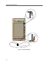
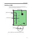
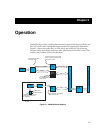
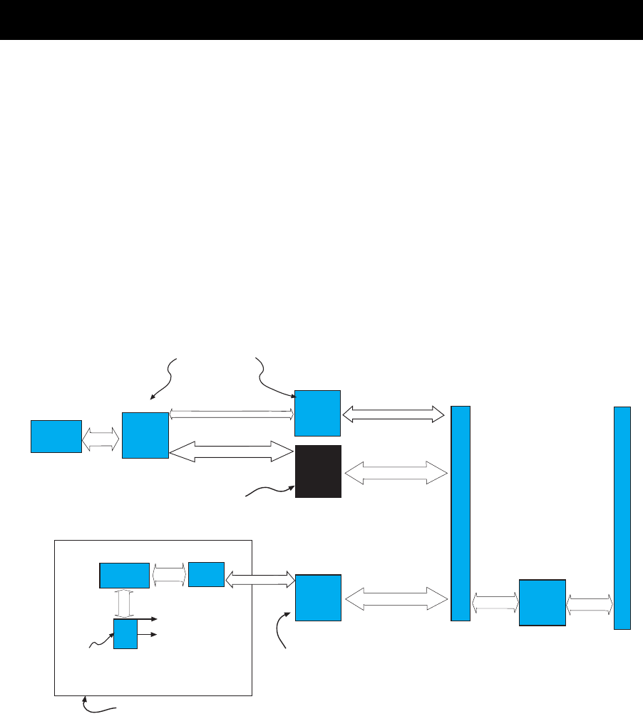
Figure 3-1 shows the trafÞc ßow of ATM cells in the 9A656-04. The following
sections brießy describe the functions of the i960 Processor, the ASICs, the CTM
and how they relate to ATM cell trafÞc ßow.
Figure 3-1. 9A656-04 Block Diagram
TDM Bus
Phycsical
Connection
to Network
ATM CELLS
ATM CELLS
UTOPIA
ASICs
Separates/assembles
cell header data
Translates headers and provides
routing information to move ATM
cells out of the TDM
TDM
ASIC
Segments and reassembles
data into ATM cells
SARI
ASIC
DATA
To SMB-1 & 10
To Z-80 Processor
DATA
DATA
CTM BACKPLANE INTERFACES
CTM
ASICs
ROUTING INFORMATION
CELL HEADER INFORMATION
Queue
ASICs
Provides translation between
the I/O ATM bidirectional data
and the TDM
DATA
CPU Interface
CPU
i960
Provides management and
configuration interface for
the 9A656-04
Shared DRAM
SAR