


15DOC.IG.QC01.1 Rev.: B December ‘06
En
Minimum operating values:
- Control supply:
Umin = 6 VDC
Imin = 1 mA
- Power supply:
Umin = 13.5 VDC
Imin = 33 mA
Cable range:
Wire range: 2.5mm
2
max.
Solid / Stranded wire: 0.2-3.3mm
2
or
24-12 AWG
Note:
* Use approved barrier according
EN60947-5-6 (NAMUR) for appropriate
signal level. Un = 8.2VDC
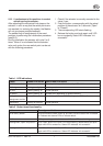
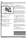
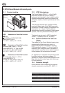
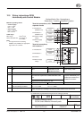
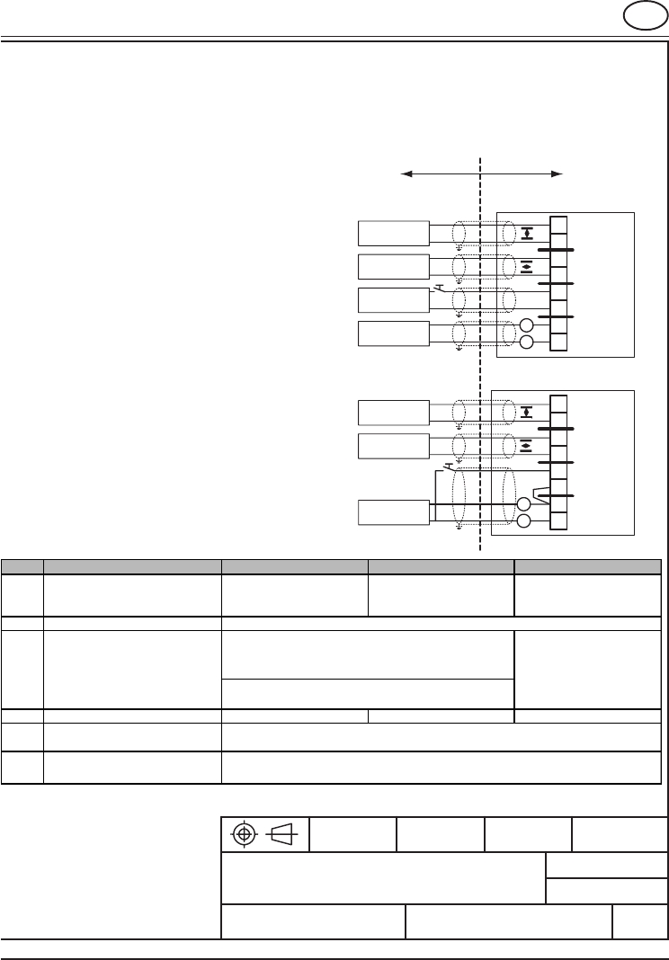
12.5 Wiring instructions QC04
Intrinsically safe Control Module
Format :
Title :
Rev. :
Drw nr.
Drn.:
Scale :
Date :
ENOC nr.:
State :
A4
Par. :Date :
www.FieldQ.com
Home page:
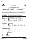
Control Drawing FieldQ
Certified Document:
No modification permitted without reference to the certifying authority.
+
-
1
2
3
4
5
6
7
8
+
-
1
2
3
4
5
6
7
8
Unclassified or Non
Hazardous Location
Hazardous or
Classified Location
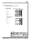
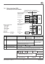
Terminal connections, with
seperate circuits
1-2 Feedback 2*
(EN60947-5-6)
3-4 Feedback 1*
(EN60947-5-6)
5-6 Control supply
voltage
7-8 Power supply
voltage
Terminal connections,
with common “-”
1-2 Feedback 2*
3-4 Feedback 1*
5-6 Control
7-8 Power supply
voltage
C0542-07
IS Approved
Barrier
IS Approved
Barrier
IS Approved
Barrier
IS Approved
Barrier
FieldQ
Control
Module
QC04
IS Approved
Barrier
FieldQ
Control
Module
QC04
Notes: CSA FM ATEX
1 Installation must be inaccordance
with:
Canadian Electrical Code,
Part1
National Electrical Code
(ANSI/NFPA 70) and
ANSI/ISA RP12.06.01
The national wiring practices
of the country of use
2 Before operation:
4 Intrinsically safe equipement Must be CSA Approved Must be FM Approved Must be ATEX Approved
Uo =< Ui Io =< Ii Po =< Pi
Co >= Ci + Cable Lo >= Li + Cable
6 When multiple barriers are used:
5
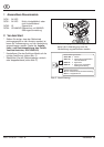
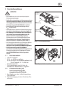
The control module in combination with the pneumatic module must be mounted properly.
3
Barrier I.S. Entity Parameters must
meet the following conditions:
* Each I.S. Circuit must use shielded, twisted pairs
* Cable insulation and shielding must extend to within paritioned area of terminals
Barriers: Must be FM/CSA Approved and installed in an enclosure
that meets the requirements of ANSI/ ISA S82.01/CEC
part1.
Control equipment connected to the barrier must not use
or generate more than 250Vrms or Vdc.
Must be certified by an
European Notified body and
installed per manufacturer’s
installation instructions
IS Approved
Barrier
IS Approved
Barrier
A
27/06/2006
QC 04 Smart Modules Intinsically safe