


5DOC.IG.QC01.1 Rev.: B December ‘06
En
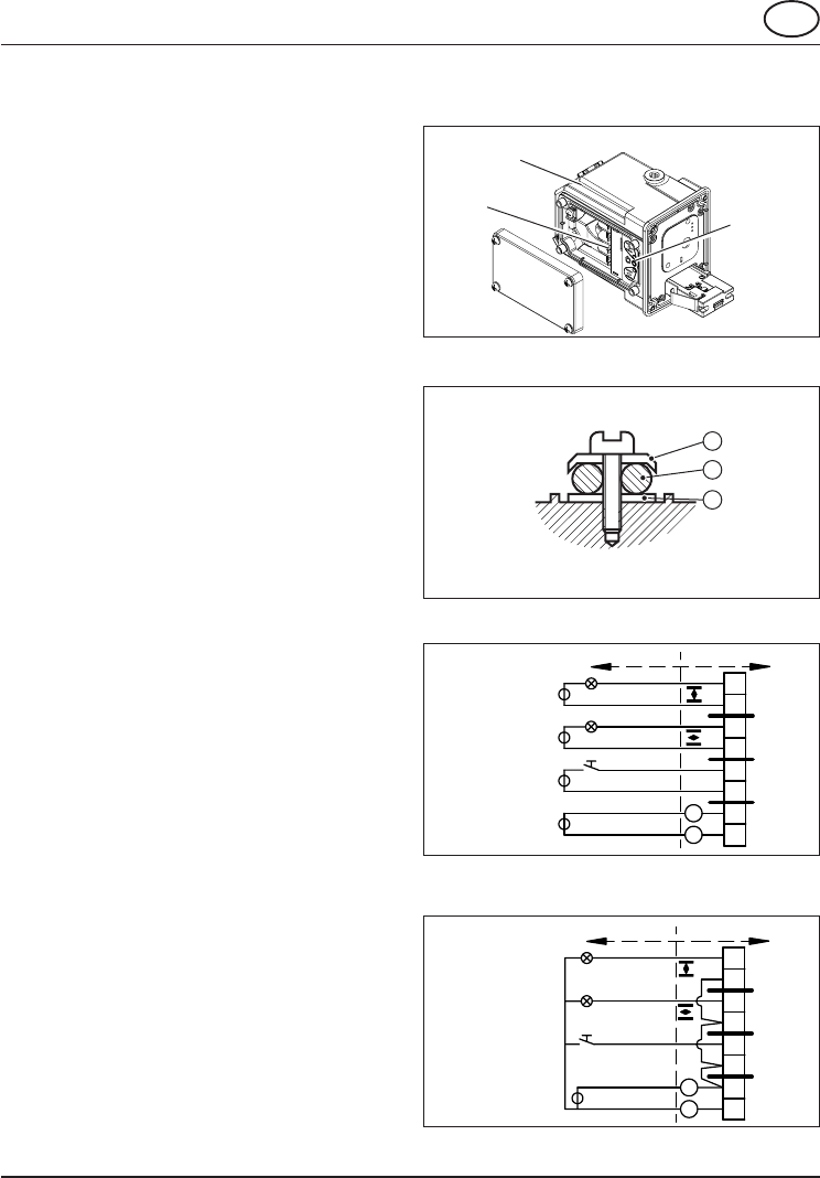
+
-
1
2
3
4
5
6
7
8
0.5 A
max.
15VA
max.
24 VDC +/- 15%
0.5 A
max.
15VA
max.
+
-
24 VDC +/- 15%
1
2
3
4
5
6
7
8
0-30 VDC/VAC
0.5 A
max.
15VA
max.
24 VDC +/- 15%
0-30 VDC/VAC
0.5 A
max.
15VA
max.
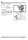
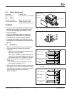
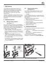
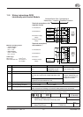
Control Module
Type Label
Terminals
Status LED
2
1
3
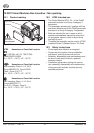
4.3 Wiring dimensions
Solid wire : 2.5mm
2
max.
Stranded wire : 0.2-3.3mm
2
or 24-12 AWG
4.4 Tools
Tool for terminals : Screw driver 0.6 x 3.5
Tool for cover screws : Screw driver for cross
slotted Phillips screws nr. 2
WARNING:
* Do not put the Control Module and the Pneumatic
Module in direct contact with magnetic material.
This can cause damage or malfunction of the
position feedback.
* If the Control Module is used in a manner not
specified by the manufacturer, the protection
provided by the equipment may be impaired.
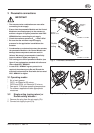
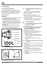
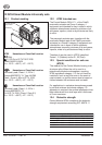
* If required, mount earth wire (1) between top (2)
and bottom (3) ring of earth wire connection (see
figure 6).
4.5 Procedure
1 Remove Control Module cover (see figure 5).
2 Guide the cable(s) through the electrical
entry(ies).
- Use and mount cable glands as required by
national or local legislation.
- When IP65 / NEMA4X ingress protection is
required, the electrical entries must be fitted
with glands rated IP65 / NEMA4X or higher.
3 Make the electrical connections as shown in
figure 7 or 8.
- For hazardous area connections, see the
instructions in chapter 10 or 11.
4 Mount the Control Module cover to the housing
(see figure 5) or continue with chapter 5. Take
care that the cover seal is in place to comply to
dust and water tightness according to
IP65 / NEMA4X.
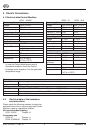
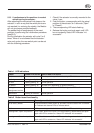
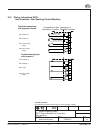
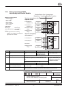
Field wiring Unit wiring
1-2 Feedback 2
3-4 Feedback 1
5-6 Control supply
voltage
7-8 Power supply
voltage
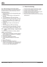
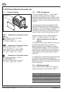
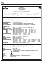
Field wiring
Unit wiring
1-2 Feedback 2,
3-4 Feedback 1
5-6 Control
7-8 Power supply
voltage
Fig.7: QC01 electric connections, seperate
circuits
Fig.8: QC01 electric connections, common “-”
Fig.5: Terminal connections behind cover.
Fig.6 Earth wire connection