


3DOC.IG.QC01.1 Rev.: B December ‘06
En
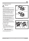
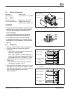
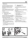
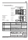
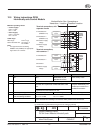
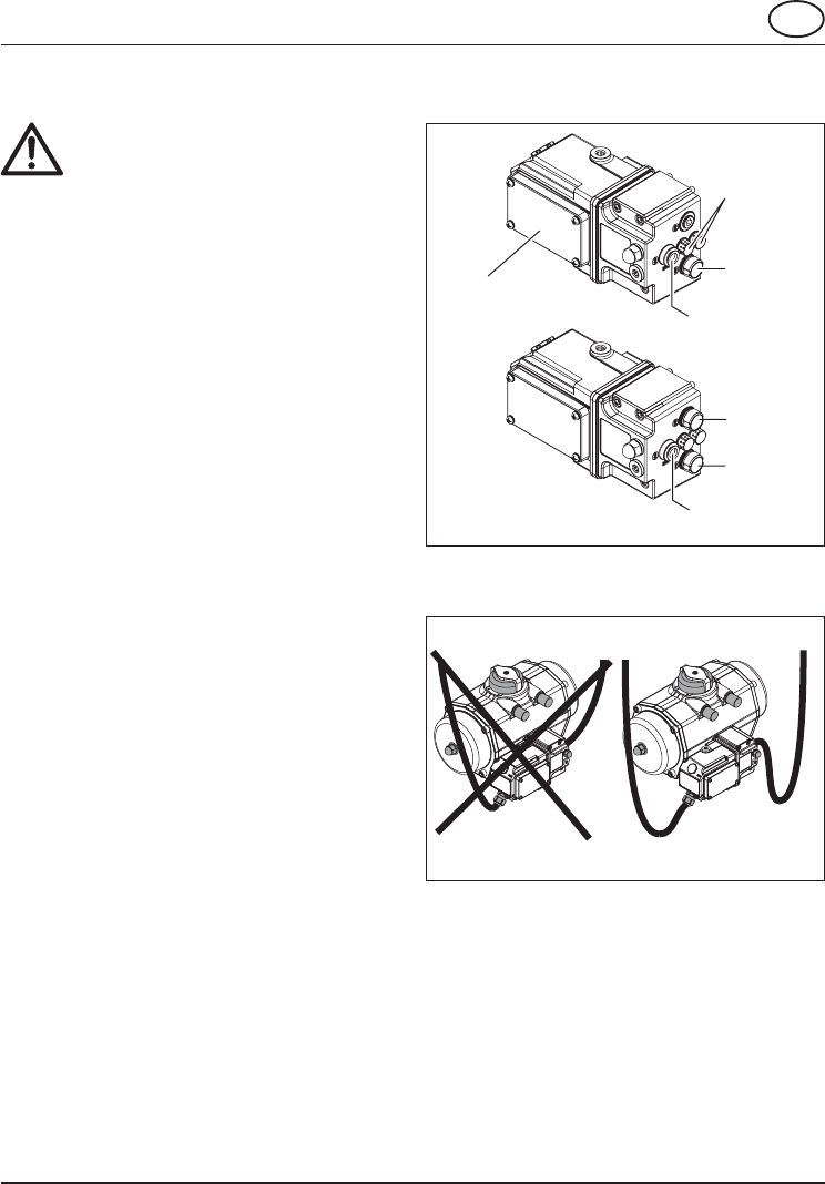
Fig. 3: Pneumatic connections
Double
acting
Control
Module cover
Single
acting
Ps
1/4”BSP or 1/4”NPT
Ra
Rb
Ps
1/4”BSP or 1/4”NPT
Rb
Venting
ports
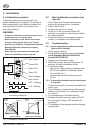
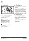
OK
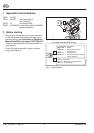
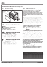
Fig 4 Install drip loops
3 Pneumatic connections
IMPORTANT
* The actuator/valve combination can move after
connecting the air supply.
* Ensure that the pneumatic Module and the Control
Module are mounted properly to the actuator to
achieve a degree of ingress protection rated IP65 /
NEMA4X before connecting the air supply.
* Check the maximum pressure P
max
= 8bar/116Psi
* Be sure that the minimum required supply
pressure for the application is available at the
actuator.
* Condensation or moisture that enters the actuator,
the pneumatic Module or the Control Module can
damage these components and can result in
failures. We strongly recommend to install drip
loops in cables in pipes (see figure. 4).
* The venting ports on the pneumatic Module (see
figure 3) are equipped as standard with silencers/
filters rated IP65 / NEMA4X.
* In case IP65 / NEMA4X ingress protection is
required, the exhaust ports Ra and Rb and the
electrical entries must be fitted with devices rated
IP65 / NEMA4X or higher.
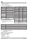
3.1 Operating media :
* Air or inert gasses.
* QC01, air filtered at 50 micron.
QC03 and QC04, air filtered at 25 micron.
* Dew point 10 K below operating temperature.
* For subzero applications take appropriate
measures.
3.2 Single acting (spring return) or
Double acting actuator :
1 Remove the plug from the air supply (Ps).
2 Connect air supply to port (Ps).