


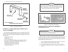


With some accessory points, the voltage only drops when the
ignition switch is in the START position. A connection point
should be used where the voltage is completely off when the
ignition switch is in the START position.
NOTE
Certain problems may be encountered when accessory equip-
ment is connected to the ignition or accessory lines of the vehicle,
where these lines may have large filter capacitors or a leakage
path present.
If the radio does not turn off within a reasonable amount of time
after the ignition is turned off, first try a different accessory or
ignition sense pick up point in the vehicle. Many vehicles have
more than one circuit that is switched by the ignition switch, and
one may be available that does not have large filter capacitors or
a leakage path present.
If a different pickup point cannot be found, then add a 470-ohm
1-watt resistor from the ignition sense pickup point to ground.
This will discharge the capacitor(s) or reduce the leakage voltage
to a low value. Current drain through this resistor will be minimal
(less than 0.03A) when the ignition is switched on.
CAUTION
10
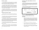
OPTIONAL ACCESSORIES
AC POWER SUPPLY (12 VOLTS AT 13 AMPS)
OPTION PS1C (PS01) (19A704647P2) 121 Volts, 60 Hz
OPTION PS1D (PS02) (19A704647P3) 121/242 Volts,50/60 Hz
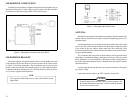
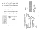
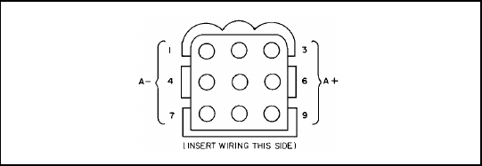
1. An empty connector housing and terminals are provided with the
power supply. Crimp three terminals on the end of the 9 foot power
cable provided with the radio. An optional 20 foot cable is available.
2. Insert the orange and red leads into pins 3, 6, or 9 of the connector
housing. Insert the black lead into pins 1, 4, or 7. Figure 10 provides
an illustration of the empty connector housing which plugs into J1 of
the power supply.
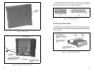
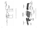
DESK MICROPHONE OPTION MC1M (MC03)
(19B851086P10)
1. The desk microphone plugs into the microphone jack on the bottom
of the radio. Remove the standard microphone and reuse the same
cable clamp for strain relief.
2. If needed, adjust the microphone gain depending on the normal
talking distance from the microphone. Access the gain control
through the small hole on the bottom of the microphone base.
3. The microphone audio is normally switched off when the PTT button
is released. If the microphone audio needs to be active at all times, a
jumper must be placed across the switch inside the microphone.
Figure 10 - Rear View of Empty Connector Housing
15