


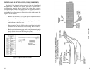

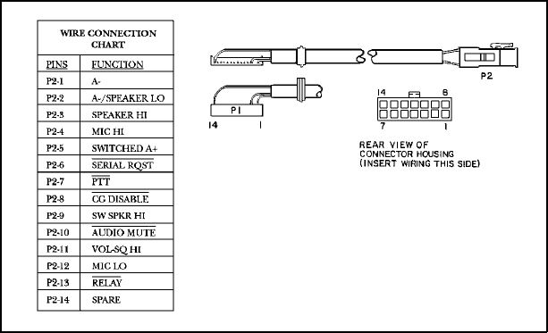
OPTION CABLE OPTION CC3N (CC08) (19C85158P3)
The Option Cable brings all option connections from the System Board
through the back of the radio to the outside. This cable is required with all
external options. Supplied with the Option Cable is the empty connector
housing which plugs into P2 of the Option Cable. Pins supplied on the ends of
the wires of each option (Molex #39-00-0060) are inserted into this connector
housing. Refer to the Interconnection Diagram in the back of this manual. See
Figure 11 for pin locations.
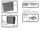
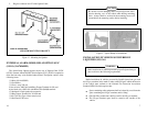
1. Remove the bottom cover of the radio by removing the two bottom
cover retaining screws. Refer to Figure 8.
2. Remove the rubber plug from the slotted opening in the rear of the
radio adjacent to the power cable.
3. Plug the Option Cable into J905A on the System Board and push the
strain relief on the cable into the slotted opening. Refer to Figure 9.
4. Before replacing the bottom cover, check to see if the particular option
being added requires unplugging the internal speaker or changing a
jumper (Refer to the section describing the option).
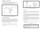
Figure 11 - Option Cable Pin Locations
16
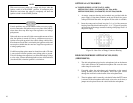
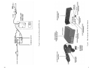
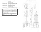
Figure 3 - Power Cable
9