


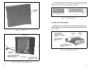
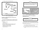

The accompanying illustrations should help you in your installation.
PLANNING THE INSTALLATION
Before starting, plan your installation carefully so that it will be:
••
Safe for the operator and passengers in the vehicle.
••
Safe to operate within easy reach of controls and microphone.
••
Protected from damage from water.
••
Easy for the serviceman to service.
••
Oriented to minimize refections in LCD display.
••
Neat
••
Out of the way of auto mechanics.
EQUIPMENT REQUIRED
The equipment required for installing the radio is:
••
Electric Drill
••
No. 31 (1/8-inch) drill for No. 8 screws
••
No. 27 (9/64-inch) drill for No. 10 screws
••
Phillips screwdriver
••
Crimp tool for terminals and antenna connector.
••
No. 20 TORX
®
driver or 1/4-inch HEX driver for mounting radio
••
5/8-inch punch or hole saw for rubber grommet
It is suggested that you take advantage of the experience of one of the many
authorized General Electric Service Stations located throughout the United
States by having them install the equipment.
TORX
®
Trademark of CAMCAR Division, TEXTRON, Inc.
Interference with Vehicular Electronics - Electronic fuel injec-
tion systems, electronic anti-skid braking systems, electronic
cruise control systems, etc., are typical of the types of electronic
devices which may be prone to malfunction due to the lack of
protection from radio frequency energy present when transmit-
ting. If the vehicle contains such equipment, consult the dealer
for the make of the vehicle and enlist his aid in determining if
such electronic circuits will perform normally when the radio is
transmitting.
WARNING
6
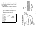
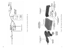
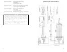
1. Install the Option Cable CC3N (CC08) in the radio.
2. Fasten the relay in the desired location, close to the voltage source,
using one #8 x 3/4 inch self-tapping screw.
3. Crimp an insulated 1/4 inch spade tab receptacle to one end of the
#18 red wire. Connect the receptacle to relay lug #86. Cut the red lead
so the fuse assembly is close to the voltage source. Install the fuse
holder. Attach the other end of the fuse lead to the voltage source with
appropriate hardware. See Figure 14.
4. Insert the black wire with the Molex terminal into pin 13 of the option
connector housing supplied with the option cable. Plug the connector
into the option cable.
5. Crimp insulated 1/4 inch spade tab receptacle to the other end of the
black wire. Connect the receptacle to relay lug #85.
6. Connect the horn or light circuit to lugs # 30 and #87 (not 87a) using
the insulated 1/4 inch spade tab receptacles.
EXTERNAL ALARM ON/OFF SWITCH OPTION SU1F
(SU02) (19C851585P7)
The External Alarm Switch, when used with External Alarm Relay Option
SU01, allows the alarm relay to be disabled. Connect the switch in series with
the black wire from the relay. Insert the wire with the Molex terminal into pin
13 of the option cable connector housing. Splice the other switch lead to the
black wire from the relay. See Figure 14.
If External Alarm ON/OFF Switch Option SU1F (SU02) is
used in conjunction with this option, refer to External Alarm
ON/OFF Switch Option SU1F (SU02).
NOTE
The relay contact make/break current and voltage rating is 30
amps at 16 volts.
NOTE
19