


RUNNING CABLES
To assure feasibility of the cable routing you plan to use, it is suggested
that you run the cables before mounting the equipment. Be sure to leave some
slack in the cables going to the equipment so that the equipment may be pulled
out for servicing with the power applied and antenna attached.
Try to route the cables away from locations where they will be exposed to
heat (exhaust pipes, mufflers, tailpipes, etc.), battery acids, sharp edges or
mechanical damage, or where they will be a nuisance to automobile mechanics,
the driver or passengers. Keep wiring away from electronic computer mod-
ules, other electronic modules and ignition circuits to help prevent interference
to these components and radio equipment.
In addition, try to utilize existing holes in the firewall and trunkwall and
the channels above and beneath the doors. You may also use the channel
through door and window columns, where they are convenient for running
cables, unless you plan to install rigid or flexible conduit in which to run the
cables.
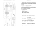
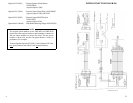
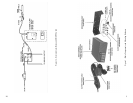
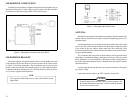
POWER AND IGNITION CABLES
The Power Cable consists of a red lead, an orange lead, a black lead, a 3
pin systems plug, and a set of fuses and fuse holders to be installed (See Figure
3).
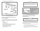
To install the Power Cable, start with the plug end of the cable at the location
of the radio and run the three leads to the firewall, drill a 5/8 inch hole and
insert a rubber grommet (customer supplied).
To install the fuses: 1)Cut off 12 to 18 inches from the red and orange
wires; 2) Strip back the insulation approximately 3/8 of an inch on each end
of the wires; 3) Insert the stripped end of each wire into the small opening at
the end of each fuse holder section and crimp the wire to the fuse holder section;
and 4) Place the fuse into the large section of the fuse holder and snap the large
end of the fuse holder to the small end of the fuse holder.
Connect the orange fused lead to the positive (+) battery terminal, and the
black to the negative (-) battery terminal. Always locate the fuse as close to
the battery as possible.
Connect the red lead to the ignition "on" sense point (preferably an
"Accessory" point on the fuse panel that is switched on when the ignition
switch is in the accessory position and in the "run" position). Locate the fuse
as close as possible to the accessory point.
8
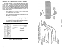
UNIVERSAL TONE CABLE OPTION CC3P (CC09)
(19C851585P5)
The Universal Tone Cable option requires the use of Option Cable CC3N
(CC08). P1 of the Universal Tone Cable plugs into P2 of the Option Cable.
The Universal Tone Cable Option provides all option connections on P2 and
a 9-pin Winchester connector for connecting to external tone encoders or
decoders. See Figure 12.
If the tone decoder requires switching the internal speaker, remove the radio
bottom cover and cut the PC run between holes 6 and 7 on the System Board.
Refer to Figure 9 for PC run identification.
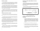
EXTERNAL SPEAKER OPTION LS1E (LS01)
(19C850550)
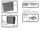
1. Mount the External Speaker where the sound will be directed to the
operator but not interfere with his vision or provide a hazard to
passengers in case of an accident. The speaker may be mounted on
the lower edge of the instrument panel, the firewall, or above the
windshield in some trucks. Use the mounting bracket as a template
for locating the mounting holes, and mount the speaker as shown in
Figure 13.
2. Install the Option Cable CC3N (CC08) if not already present.
3. Before replacing the bottom cover of the radio, unplug the internal
speaker from A5 J904 on the System Board. Refer to Figure 9.
4. Pins are supplied on the ends of the speaker leads. Push these pins
into pins 2 and 9 of the connector housing supplied with the Option
Cable. Refer to Figure 11.
Figure 12 - Tone Cable Pin Location
17