


5. Plug the connector into P2 of the Option Cable.
EXTERNAL ALARM (HORN) RELAY OPTION SU1C
(SUO1) (19A705499P1)
The Alarm Relay Option requires the the use of Option Cable CC3N
(CC08). External Alarm ON/OFF Switch Option SU1F (SU02) is required to
allow the horn relay to be disabled when desired. The Option consists of the
following items:
(1) Relay (19A149299P1)
(1) Fuse holder
(1) Fuse, 1 amp, 250 volt
4 feet red wire, AWG #18 with Ring Tongue Terminal for 3/8 stud
6 feet black wire, AWG #18 with Molex #39-00-0060 terminal
(5) Insulated 1/4 inch spade tab receptacles
(1) Ring Tongue Terminal for 3/8 inch stud
(1) #8 x 3/4 long Type A sheet metal screw
(1) Nut Plate for #8 screw
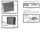
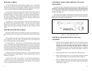
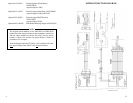
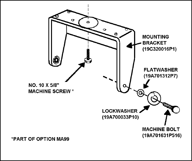
SPEAKER MOUNTING BRACKET
Figure 13 - Mounting the Speaker
18
INSTALLATION IN VEHICLES POWERED BY
LIQUEFIED (LP) GAS
Radio installations in vehicles powered by liquefied petroleum gas with
the LP-gas container in the trunk or other sealed-off space within the interior
of the vehicle must conform to the National Fire Protection Association
Standard NFPA 58 which requires that:
••
Space containing radio equipment shall be isolated by a seal from the
space containing the LP-gas container and its fitting.
••
Outside filling connections shall be used for the LP-gas container.
••
The LP-gas container space shall be vented to the outside of the
vehicle.
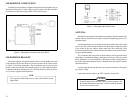
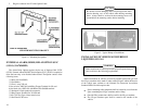
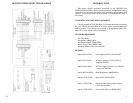
Figure 2 - Typical Hump or Dash Mount
Be careful to avoid damaging some vital part (fuel tank, trans-
mission housing, etc.) of the vehicle when drilling mounting
holes. Always check to see how far the mounting screws will
extend below the mounting surface before installing.
CAUTION
Radio installations in vehicles powered by liquefied petroleum gas
must conform to the following requirements.
WARNING
7