


13
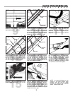
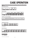
ELECTRICAL HOOKUP
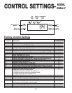
DEFROST HEATERS, 208/240 VOLTS L1
L2
RED
BLUE
EVAPORATOR FANS, 120 VOLT
WIRE NUMBERCOMPONENT COLOR CODING
BLACK
TEMPERATURE CONTROL, 120 VOLT
LIGHTS, 120 VOLT
DEFROST TERMINATION CONTROL, 120 VOLT
WHITE
3
4
11
12
19
20
21
YELLOW
YELLOW
PURPLE
ORANGE23
WIRING NUMBERS AND COLORS
EQUIPMENT GROUNDING CONDUCTOR GREEN
-
BLACK
WHITE
ANTI-CONDENSATE HEATERS, 120 VOLT
13
14
WHITE
BLACK
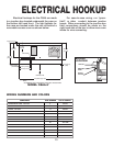
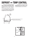
5 13/16 in [14.7 cm]
38 5/16 in
[97.3 cm]
49 1/16 in
[124.6 cm]
34 1/2 in
[87.6 cm]
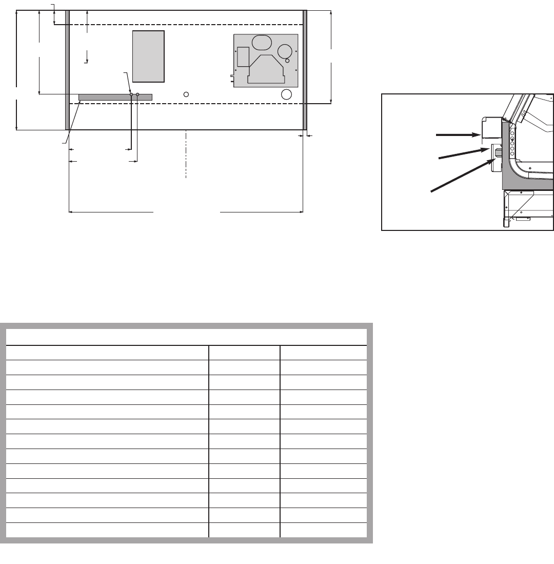
ELECTRICAL
JUNCTION BOX
(STANDARD)
25 9/16 in [64.9 cm]
28 1/16 in [71.2 cm]
FRONT OF CASE
1 1/2 in [3.8 cm]
{END}
21 1/2 in
[54.6 cm]
**
NOTES:
** RECOMMENDED STUB-UP CENTERLINE FOR ELECTRICAL AND HUB DRAINS
C
L
72 in [182.9 cm] {6' case}
MODEL OSAA-6’
REAR SILL
BALLAST
LOCATION
REMOVABLE
COVER
BALLAST
LOCATION
Electrical hookups for the OSAA are made
to a junction box located underneath the case on
the bottom left hand front. The light ballasts for
the case are located under the rear sill behind a
removable access cover as shown below.
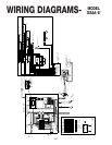
For case-to-case wiring, run “green-
field”, or other conduit, between junction
boxes. When connecting to the junction box
field connections should be made on the
right hand side of the box to allow more room
inside for wire connecting.