HUAWEI MG323 GSM M2M Module
Hardware Guide
Description of the Application Interfaces
Issue 04 (2011-08-22)
Huawei Proprietary and Confidential
Copyright © Huawei Technologies Co., Ltd.
19
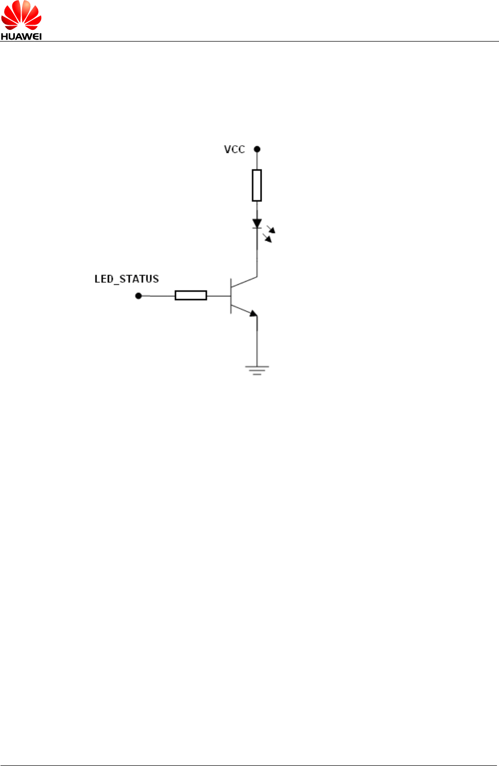
In practical application, the LED_STATUS pin cannot be directly used to drive the
status LED. The LED_STATUS pin needs to be used with a triode. To select a
suitable current-limiting resistor for the LED, check the actual voltage drop and rated
current of the LED. Figure 3-6 shows the driving circuit.
Figure 3-6 Driving circuit
3.6 UART Interface
3.6.1 Overview
The MG323 module provides the RS-232 UART1 (8-wire UART) interface for one
asynchronous communication channel. As the UART1 interface supports signal
control through standard modem handshake, AT commands are entered and serial
communication is performed through the UART1 interface. The UART1 has the
following features:
Full-duplex
7-bit or 8-bit data
1-bit or 2-bit stop bit
Odd parity check, even parity check, or non-check
Baud rate clock generated by the system clock
Direct memory access (DMA) transmission
Baud rate ranging from 600 bit/s to 230400 bit/s (115.2 kbit/s by default)
Self-adapted baud rate ranging from 1200 bit/s to 115.2 kbit/s
Table 3-5 lists the UART1 interface signals.


