


HUAWEI MG323 GSM M2M Module
Hardware Guide
Description of the Application Interfaces
Issue 04 (2011-08-22)
Huawei Proprietary and Confidential
Copyright © Huawei Technologies Co., Ltd.
21
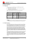
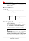
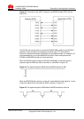
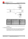
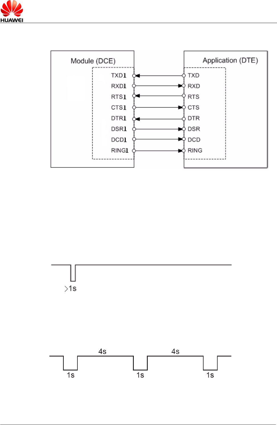
Figure 3-7 Connection of the UART1 interface in the MG323 module (DCE) with the
host (DTE)
The RS-232 chip can be used to connect the MG323 GSM module to the RS-232-C
interface. In this connection, the transistor-transistor logic (TTL) level and the
Electronic Industries Association (EIA) level are converted mutually. For example, it is
recommended that you use the MAX3232 chip with a 2-wire serial port and the
SP3238 or MAX3238 chip with an 8-wire serial port.
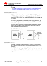
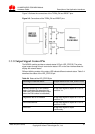
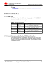
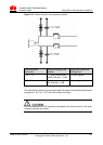
When an MG323 module receives an SM (Short Message), a low-level signal is
output through the RING (pin 38) for less than 1s, as shown in Figure 3-8 .
Figure 3-8 The signal through the RING after the MG323 receives an SM
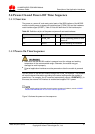
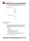
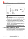
When an MG323 Module receives a voice call, a periodical low level signal for 1s and
a high level signal for 4s are output by RING, as shown in Figure 3-9 .
Figure 3-9 The signal through the /RING after the MG323 receives a voice call