


HUAWEI MG323 GSM M2M Module
Hardware Guide
Description of the Application Interfaces
Issue 04 (2011-08-22)
Huawei Proprietary and Confidential
Copyright © Huawei Technologies Co., Ltd.
23
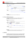
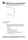
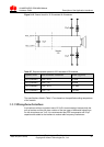
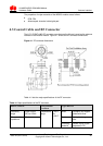
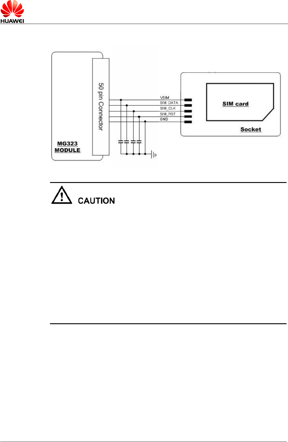
Figure 3-10 Circuit of the SIM card interface
To meet the requirements of 3GPP TS 51.010-1 protocols and electromagnetic
compatibility (EMC) authentication, the SIM card socket should be placed near the
B2B connector interface (it is recommended that the PCB circuit connecting the
B2B connector interface and the SIM card socket not exceed 100 mm), because a
long circuit may lead to wave distortion, thus affecting signal quality.
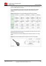
It is recommended that you wrap the area adjacent to the SIM_CLK and
SIM_DATA signal wires with a ground wire. The GND pin of the SIM card socket
and the GND pin of the SIM card must be well connected to the power GND pin
supplying power to the MG323 module.
A 0.1 µF capacitor or a 0.22 µF capacitor is placed between the VSIM and GND
pins in parallel. Three 33 pF capacitors are placed between the SIM_DATA and
GND pins, the SIM_RST and GND pins, and the SIM_CLK and GND pins in
parallel to filter interference from RF signals.
You do not need to pull the SIM_DATA pin up during design as a 15000-ohm
resistor is used to connect the SIM_DATA pin to the VSIM pin.
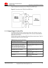
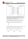
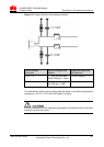
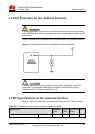
3.7.3 ESD Protection for the SIM Card Interface
It is recommended that you take electrostatic discharge (ESD) protection measures
near the SIM card socket. Figure 3-11 shows ESD protection circuit of the SIM card,
in which the transient voltage suppressor (TVS) diode is placed as near as possible
to the SIM card socket, and the GND pin of the ESD protection component is well
connected to the power GND pin that supplies power to the MG323 module.