


3. TECHNICAL BRIEF
- 19 -
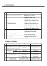
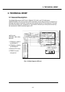
3.2 GSM Mode
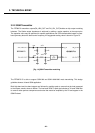
3.2.1 GSM Receiver
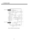
The Dual-mode U250/KU250’s receiver functions are split among the three RFIC’s as follows:
• GSM-900, DCS-1800, and PCS-1900 UMTS-2100 modes use the RTR6275 IC only. Each mode has
independent front-end circuits and down-converters, but they share common baseband circuits (with
only one mode active at a time). All receiver control functions are beginning with SBI
2
-controlled
parameters.
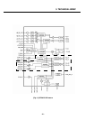
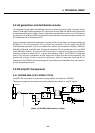
RF Front end consists of antenna, antenna switch module(D5011) which includes three RX saw
filters(GSM900, DCS and PCS). The antenna switch module allows multiple operating bands and
modes to share the same antenna. In U250/KU250, a common antenna connects to one of six paths:
1) UMTS-2100 Rx/Tx, 2) GSM-900 Rx, 3) GSM-900 Tx, 4) DCS-1800 Rx, and 5) DCS-1800 Tx, PCS-
1900 Tx(High Band Tx’s share the same path), 6) PCS-1900 Rx. UMTS operation requires
simultaneous reception and transmission, so the UMTS Rx/Tx connection is routed to a duplexer that
separates receive and transmit signals. The GSM900, DCS, and PCS operation is time division
duplexed, so only the receiver or transmitter is active at any time and a frequency duplexer is not
required.
2
The RFIC operating modes and circuit parameters are MSM-controlled through the proprietary 3-line Serial Bus Interface (SBI). The Application
Programming Interface (API) is used to implement SBI commands. The API is documented in AMSS Software - please see applicable AMSS
Software documentation for details.
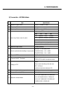
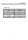
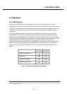
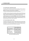
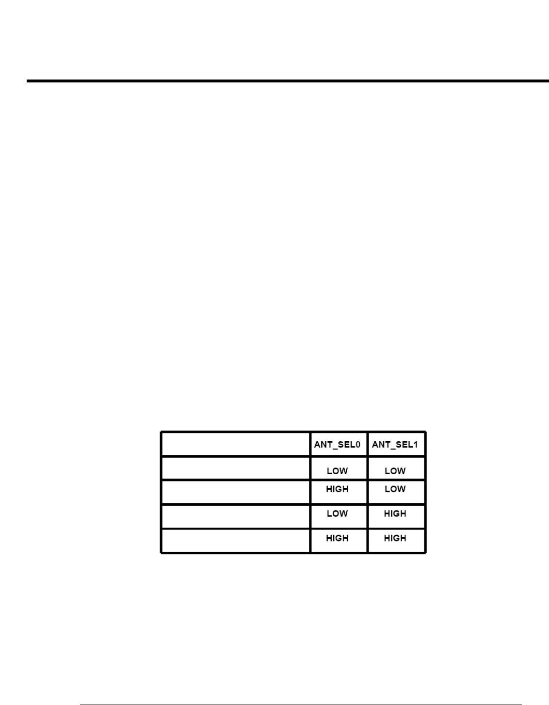
[Table 1.1] Antenna Switch Module Control logic
GSM 1800 / GSM1900 RX
GSM 900 RX
GSM 900 TX / WCDMA
GSM 1800 / GSM 1900 TX