


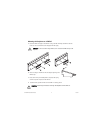
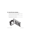

C. Use a separate power supply for each module that needs external power.
D. Refer to the operating instructions for the power requirements of each I/O module. If a
module requires external power, connect a power supply to the V and C inputs on the
connector block for that module. If you want to power field I/O devices from a connector
block, supply power to the connector block, and then connect the connector block V and C
output terminals to the field device.
9
cFP-20xx Quick Start Guide
©
National Instruments Corporation
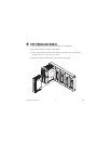
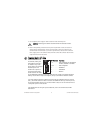
CCAAUUTTIIOONN
Cascading power defeats isolation between the cascaded modules.
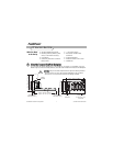
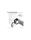
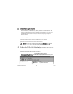
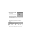
PPoowweerriinngg UUpp tthhee ccFFPP--2200xxxx
Check the DIP switches on
the controller, making sure
that the RESET IP switch is
not enabled. Plug in each
power supply to the Compact
FieldPoint system. The
cFP-20
xx
runs a power-on
self test (POST) that takes
several seconds. You should
see the POWER and STATUS LEDs come on. After about five seconds, the STATUS LED begins
flashing. The cFP-20
xx
is ready to be configured, and you can install the FieldPoint software.
If you have already assigned an IP address to the cFP-20
xx,
the STATUS LED turns off, and the
A, B, C, and D LEDs come on for about 15 seconds as LabVIEW RT starts up. Once they turn off,
the I/O module READY LEDs come on, and the cFP-20
xx
is ready for use. The total boot time for
a configured system is 30–45 seconds.
If the STATUS LED does not light up as described here, refer to the
cFP-20xx and cFP-BP-x
User Manual.
7
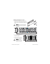
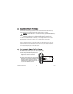
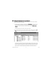
12345
687
ON
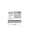
DDIIPP SSwwiittcchheess FFuunnccttiioonnss
1, 2 . . . . . . . . . .User-configurable on cFP-2000 and
cFP-2010; disabled on cFP-2020
3, 4, 5 . . . . . . . .User-configurable
6 . . . . . . . . . . . .DISABLEVI
7 . . . . . . . . . . . .SAFEMODE
8 . . . . . . . . . . . .RESETIP