


CONFIDENTIAL
Service & Analysis Center Europe
Training Team
version 1.0 / 05.11.1999 Page 30 of 37
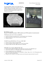
Recommendation for repair actions in the RF- area
To prevent some additional faults please take care of following recommendations for repairing the RF-area
•
Don't use so much flux that it will go through the board and soiled the keyboard area
•
Clean after every repair time the rest of the flux from PCB
•
Don't make any loose wiring connection on the board
•
To change some components it is necessary to remove the shield from the PCB, use matching nozzles for the
solder machine. Don't cut it partially and solder the "old" part back or make some unqualified work
•
Use a new shield after removing
Low receiver signal strength indicator
Antenna faulty / wrong - Tuning
•
Check the fixed position of the antenna,
don't touch the conducting area with the fingers
•
Check the antenna spring connector X501, change it if bent
•
Check the receiver signal indicator with a new antenna
•
Retune the handset
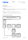
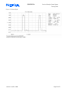
No Service
Set first the RF-Generator to a high RF-Level output e.g. –40dBm
Set the module with wintesla as follow mode: Initialise/ Local mode/ Testing/ RF Controls…/ Active unit "RX"/
Operation Mode "continuous
"
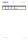
13MHz VCTCXO G701 out of range
•
Check the 13MHz reference frequency pin 15 N700 (SUMMA) or pin 2 of G750, a frequency error
higher +-50Hz can create deviation of the Intermediate frequencies
•
View also SB 18 "The old version 'A' VCTCXO (type number: NGK3092A) should be replaced with a new version 'B'
VCTCXO (type number: NGK3092B)"
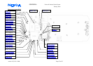
No RX (no Rx calibration…RSSI reading highest value)
N600 CRFU / faulty / poor soldering
•
Check the incoming RF- Channel frequency on pin 27 N600
•
Check the LNA_AGC voltage 2,8V DC pin 28 N600
•
Check the VRX_1 voltage 2,8V pin 15,16,23, 33, 38,45,46 N600
•
Check the LNA_OUT frequency pin 23 N600 and input on pin 18, 19.
An attenuation from aprox. 10-15dBm between signal input and output is normal!
•
Check the UHF LO frequency (2036MHz GSM900 CH60) pin 3 N600 approx. –20dBm.
No frequency deviations are allowed!
•
Check the outgoing 71MHz Intermediate Frequency on pin 15, 16 N600
•
Check the soldering of N600 or change it
Z700 / faulty / poor soldering
•
Check the 71MHz IF frequency on Z700. The normal attenuation between input and output are ≈15dBm
•
Check the components C701, C704,C149, L701, R701 if the signal amplitude is different between the two lines
•
check the soldering of Z700 or change it